
The ABS block is located between the brake master cylinder and the brakes. The presence of ABS does not affect the design of the vacuum booster and brake master cylinder.
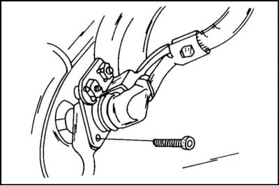
The front wheel sensors are located in the steering knuckles as shown. They control the number of revolutions of the wheels of the car through the gear rims mounted on the front drives.

The rear wheel sensors are attached to the rear axle carrier as shown.
In the event of malfunctions in the operation of the ABS, it is necessary to contact the Opel car repair shop, which has special diagnostic equipment. If the ABS warning light comes on, you can continue driving, but the system does not work.
Replacing the front wheel speed sensors
The front wheel sensors are removed and installed as follows:
Removing
1. Disconnect the ground cable from the battery.
2. Raise and place the front of the vehicle on stands.
3. Remove the wheel, ensuring access to the sensor cable.
4. Remove the plug connection in the wheel housing from the holder and unclip it with a screwdriver.
5. If there are several plug connections, find out which one belongs to the ABS sensor.
6. Disconnect the cable from the mount.
7. Unscrew the sensor mounting bolt with a socket wrench and carefully separate it with a screwdriver.
Installation
The sensor is installed in the reverse order of removal.
1. Tighten the fastening bolt to a torque of 9 Nm.
2. Be careful not to twist the sensor cable. The cable is marked with a white line.
3. When tightening the cable fixing bolts, pay attention to the different tightening torques.
4. The lower cable fastening bolt is fastened with a torque of 27 Nm., the upper cable with a torque of 6 Nm.
5. Make sure that the speed sensor is not dirty or damaged.
6. After completing the work, turn the ignition key to the working position and check that the ABS indicator turns off.
Replacing rear wheel speed sensors
Removing
1. Disconnect the ground cable from the battery, lift and place the rear of the car on stands.
2. Locate the sensor cable and disconnect the plug connection, disconnect the cable from the mount.
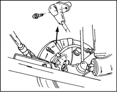
3. Unscrew the sensor. The location of the sensor on the rear suspension is shown in the illustration.
Installation
The sensor is installed in the reverse order of removal.
1. Be careful not to twist the cable when connecting. For proper routing, the cable is marked with a white line.
2. Tighten the sensor fastening bolts to 22 Nm, cable fastening bolts to 27 Nm.
Notes on wheel speed sensors
The wheel speed sensor consists of a magnetic core and a coil. The principle of operation of the sensor is illustrated by the diagram in the illustration.
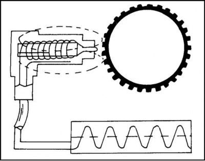
Diagram explaining the principle of operation of the wheel speed sensor
The protrusion of the pole piece is surrounded by a magnetic field. In the process of rotation, the teeth of the gear rotor cross the magnetic field. This leads to field distortion, which in turn indicates an alternating voltage in the sensor coil. The frequency of voltage changes corresponds to the number of revolutions of the wheel. The relevant information is sent to the control unit.
Toothed rotors (otherwise they are called impulse rings) have 54 teeth. At the front, the rotors are mounted with three bolts to the inside of the hub/brake disc assembly. Behind the gear rotors are pressed onto the drives.
Replacing the front wheel sensor rotor
1. Remove the front hub as described in the appropriate section.
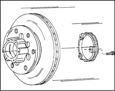
2. Remove the rotor from the inside of the wheel hub.
3. If the removed rotor is installed backwards, the tooth surfaces must be checked. They must not be damaged.
4. When installing, tighten the bolts to a torque of 18 Nm.
Replacing the Rear Wheel Sensor Rotor
1. Raise and place the rear of the vehicle on stands.
2. Remove the rear drive as described in the appropriate section.
3. Remove and install the gear rotor in connection with the replacement of the drive bearing.
4. This work is also described in Chapter Brake system
Visitor comments