
The ABS 8.0 system is a modular system with 8 solenoid valves. According to its basic design, it corresponds to the ABS 5.3 system and is also additionally purchased with an exchange rate stability system (ESP).
With the introduction of the ABS 8.0 ESP system, for the first time in Opel vehicles, when adjusting the brake system, the parameter «Brake system temperature».
By measuring the temperature in the hydraulic unit, it is possible to determine from the characteristic whether there is a risk of overheating of the brake system when driving downhill.
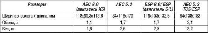
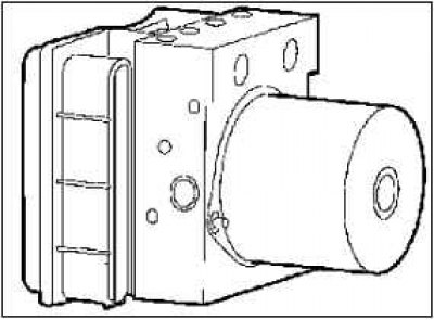
The ABS control unit/hydraulic unit assembly has been modified. The weight of the ABS control unit/hydraulic unit assembly has been reduced by 25% thanks to modern microprocessor technology. At the same time, the external dimensions have changed and, consequently, the volume of the unit has decreased by 30% compared to the ABS 5.3 system.
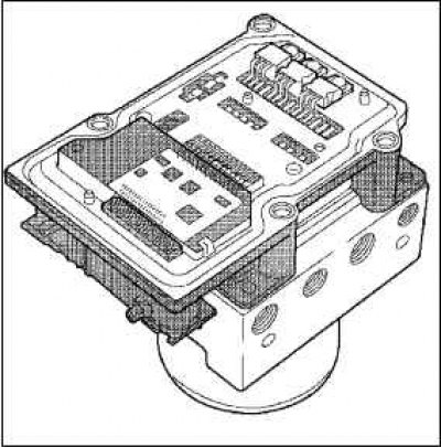
The ABS control unit can be removed from the hydraulic unit when assembled thanks to the horizontal mounting position in the Corsa-C model.
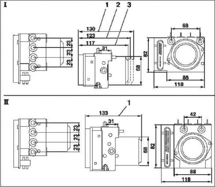
Externally, the ABS 8.0 system and the ABS 8.0/ESP system differ not only in size.
The diameter of the hydraulic connections on the ABS control unit from the brake master cylinder in the ABS 8.0 system is smaller than in the ABS 8.0/ESP system.
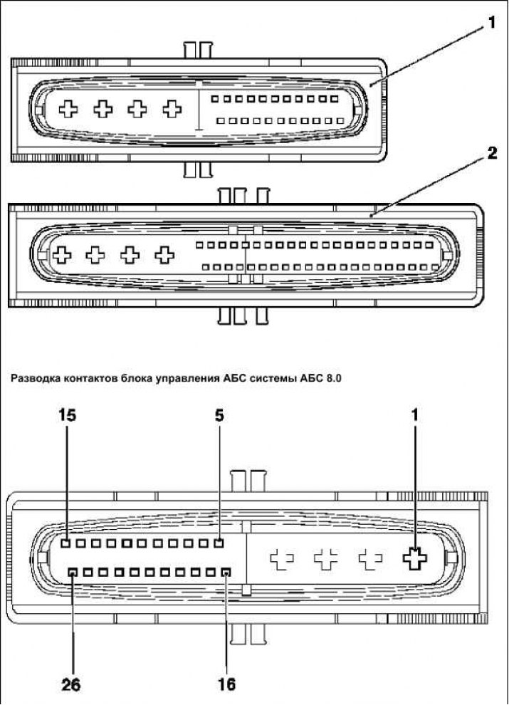
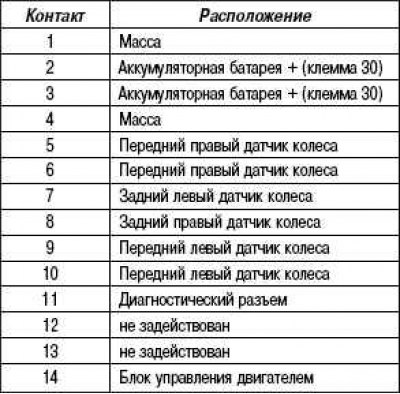
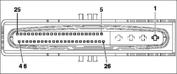
The electrical connection on the ABS control unit is 26-pole in ABS 8.0 and 46-pole in ABS 8.0/ESP.
Dimensions and weight
Depending on the version of the ABS 8.0 system, the weight also differs.
Mounting position
The mounting position of the ABS control unit/hydraulic unit assembly in the Corsa-C model is horizontal. The motor of the hydraulic unit with its axis is mounted in a horizontal position, and the connections of the individual circuits of the brake drive point upwards. The advantage of this installation position is that the ABS control unit can be dismantled during installation or repair work without removing the entire assembly.
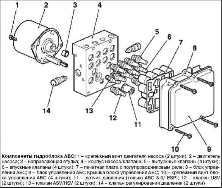
The ABS 8.0 control unit is based on the latest pulse and chip technology and is designed to connect 4 active or 4 passive wheel sensors. The Corsa-C model uses active wheel sensors. The ABS 8.0 control and monitoring function is protected by two separate microprocessors 1. These microprocessors are reprogrammed accordingly. Individual components of the ABS control unit are not replaced. In the event of a defect, the entire ABS control unit must be replaced.
The pump motor in the hydraulic unit of the ABS 8.0 system is controlled through the pump casing. The solenoid valves of the hydraulic unit are actuated through the solenoid coils. These coils are directly connected to the solid state relay in the ABS control unit and are thus integrated into the ABS control unit.
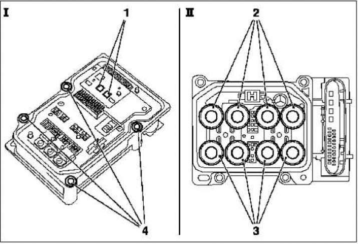
The ABS control unit is connected to the hydraulic unit with four fixing screws (4), and it can be disconnected from the vehicle's hydraulic unit and removed.
Service
During repair work, it is possible to replace the components of the ABS control unit and the disconnected hydraulic unit.
The hydraulic unit is delivered pre-charged from the service department. The ABS control unit seal is not sold separately. If there is a leak between the hydraulic unit and the ABS control unit, the complete ABS/hydro unit assembly must be replaced.
Conditions for replacing the ABS control unit
This block should only be replaced with a new block if the diagnostic result is indeterminate «ABS control unit malfunction» (when diagnosed with Tech 2 and DTC «Control unit defect») or if there is visible damage to the housing or the connector of the ABS control unit.
If the ABS control unit is disconnected from the hydraulic unit in the assembled state, attention must be paid to maximum cleanliness in the surrounding area, since even the slightest contamination in the area of the valves of the hydraulic unit can lead to incorrect functioning.
The cover of the ABS control unit must never be pushed in. This leads to externally invisible defects in the control unit (ASG). During installation, hold the ABS control unit only by the outer edge of the housing and pay attention to the installation without force.
Under no circumstances must the ABS control unit be connected to the hydraulic unit using fixing screws. This will damage the ABS control unit and/or the hydraulic unit.
The replacement of ABS 8.0 system components, especially in the area of the ABS control unit/hydraulic unit assembly, may only be carried out by trained personnel with appropriate special knowledge of replacement conditions and Maintenance Procedures.
As spare parts, use only new parts specified in the electronic spare parts catalogue.
Hydro unit
The assembled hydraulic unit is connected to the ABS control unit. With the version with ESP, the pressure sensor is no longer mounted externally on the hydraulic unit, as with ABS 5.3 TC/ESP, but integrated into the hydraulic unit. The individual components of the hydraulic unit must not be replaced or repaired. In the event of a defect, the complete hydraulic unit or the ABS control unit/hydraulic unit assembly must be replaced accordingly.
The hydraulic connections to the master brake cylinder are located on the hydraulic unit in completely different ways for ABS 8.0 and ABS 8.0 E systems. The diameter of the hydraulic connections also differs between ABS 8.0 and ABS 8.0 ESP, so that it is not possible to install the wrong version of the hydraulic unit.
The spring contact pins mounted on the end face of the ABS control unit must not touch due to possible electrostatic discharge and no measurement needs to be taken. Spring contact pins are not individually replaceable. In order to avoid damage, the gold-plated surface of the contact pins must also never be machined or treated with liquids, such as, for example, liquid for treating electrical contact connections.
Also, no measurements can be made on the plug-in contacts for the pump motor. The contacts are not replaceable and are made in the lower part of the hydraulic unit through the valve block to the ABS control unit.
ABS pressure and temperature sensor 8.0 ESP
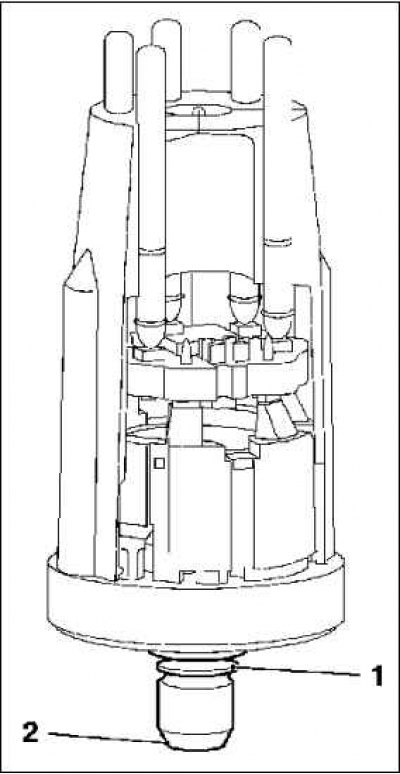
In the ABS 8.0 ESP system, the pressure sensor is no longer mounted externally on the hydraulic unit, as with the ABS 5.3 TC/ESP system, but integrated into the hydraulic unit. The electrical connection to the ABS control unit is made through gold plated spring contact pins. The pressure sensor is fixed in the hydraulic unit with self-locking 1 and cannot be dismantled. Sealing is carried out along the conical surface 2.
The temperature sensor is additionally integrated into the pressure sensor. The temperature sensor measures the temperature of the hydraulic unit. In the ABS control unit, this data is used to draw conclusions on the load of the brake system from the characteristics. In this way, for example, it is determined whether there is a risk of overheating of the brake system when driving downhill. Due to the downhill braking process, the brake discs heat up so much that the resulting heat is transferred by the brake discs through the disc wheel brake caliper to the brake fluid. Thus, the temperature in the hydraulic unit also rises.
The pressure and temperature sensor, independent of the ABS control unit, has the following properties:
self-diagnosis function;
full self-diagnosis function with detection of sensitivity errors and zero offset;
2 analog outputs for pressure;
2 digital outputs for temperature.
Technical data of the pressure sensor
Pressure sensor measuring range: (0–250) bar.
Temperature sensor measuring range: (–40...+120) °C.
Power supply: 5 V DC Current.
Service
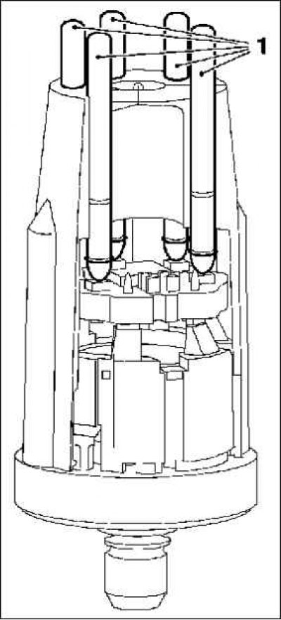
The pressure sensor cannot be replaced separately. The contact plate for the pressure sensor in the ABS unit, as well as spring contacts 1, has a gold-plated surface. It does not need to be machined.
The position of the pressure sensor must not be changed (for example, turning). The housing of the pressure sensor must also not be loaded mechanically, otherwise damage that is not visible from the outside may occur. If the pressure sensor is defective (except for leaks) the entire hydraulic unit must be replaced. If subsequently, when starting the system, damage is detected on the pressure sensor, then the ABS control unit should be replaced.
If there are signs of brake fluid leakage at the pressure sensor, the ABS control unit/hydraulic unit assembly as a set must be replaced, as in this case damage to the ABS control unit by the brake fluid can no longer be ruled out.
ABS control unit harness connector
The plug connection on the ABS control unit is made for the 26-pole ABS 8.0 1 and the 46-pole ABS 8.0 ESP 2. Both versions have 4 power contacts with one seal on the wiring harness connector. Power contact dimensions (2,8 x 0,8) mm.
For the ABS 8.0 system, 22 additional signal contacts are provided (for ABS 8.0 ESP: 42 signal contacts) with dimensions (0,63 x 0,63) mm. The signal contacts are protected by a silicone seal on the ABS control unit connector
The wiring harness connector is fixed after being put on with a plastic clip insert.
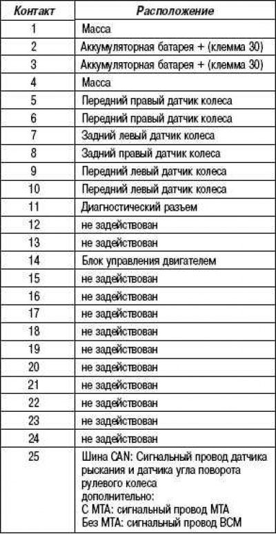
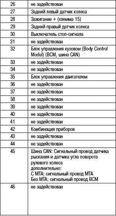
The wiring of the ABS control unit of the ABS 8.0 ESP system
See hydraulic drive block diagram - ABS 8.0.
ABS control unit harness connector
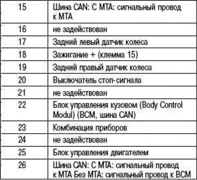
The wiring of the ABS control unit of the ABS 8.0 ESP system
Bleeding the brake system ABS 8.0 and ABS 8.0 ESP
Bleeding of air from the hydraulic actuator of the ABS 8.0 system occurs in the sequence rear right, rear left, front right and front left. In this case, a brake bleeding device, available from the service department, must be used.
The brake fluid enters the reserve tank and is compressed by the pre-pressure of the brake bleeder through the master brake cylinder and through the hydraulic unit into the wheel brake cylinder. The bleed screw for the respective brake circuit is opened (in the example for front right). All other bleed screw plugs are closed.
During pumping, you can press the pedal to maintain the pre-pressure and, therefore, to improve the result. The respective brake circuits must be bled until the brake fluid comes out and is free of bubbles and foam. Pumping should logically be repeated on the remaining 3 wheels.
The following hydraulic diagram of the ABS 8.0 system shows, as an example, the correct bleeding on the front left brake circuit.
Visitor comments