
Hydraulic modulator
Removing
Disconnect the negative battery terminal.
Remove the brake fluid reservoir cap and secure a piece of polyethylene over the filler neck with tape, or reinstall the cap. This will reduce fluid loss during operations.
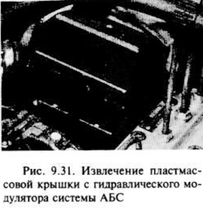
Remove the screw and plastic cover from the hydraulic modulator (pic. 9.31).
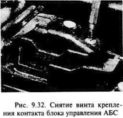
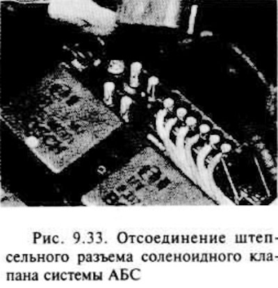
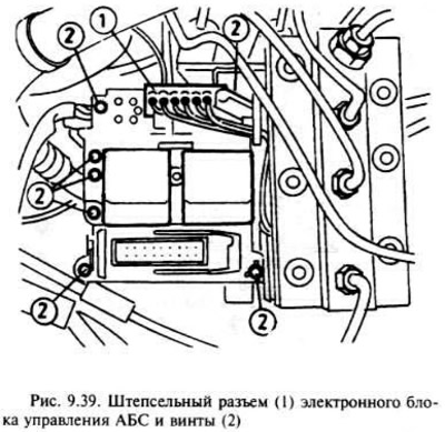
Disconnect the plug contact of the control unit and the solenoid valve. Pay attention to that. that the contact of the control unit is fixed with a screw (pic. 9.32, 9.33.).
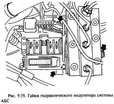
Turn away nuts and disconnect pipes of a brake liquid from the modulator. Fluid may leak, so close the hole. Move the tubes away from the modulator.
Unscrew the three nuts, then tilt the modulator slightly and remove it, separating it from the bracket, but in such a way that the nut of the ground wire is accessible (pic. 9.34, 9.35.).
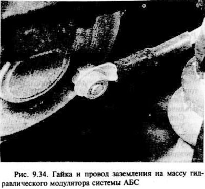
Loosen the nut and disconnect the ground wire, then remove the modulator from the vehicle, being careful not to spill brake fluid on the painted surfaces of the vehicle.
If a new modulator needs to be installed, remove the two relays on top of the old modulator and replace them with the new one. Do not attempt to disassemble the modulator.
Installation
Before installing the modulator, check that the bolts securing the support bracket to the body panel are firmly tightened. The rubber support must be in good condition. If necessary, replace it.
Installation is carried out in the reverse order of removal, taking into account the following.
Make sure the ground wire is connected before mounting the modulator to the base bracket.
Remove the plastic film from the neck of the brake fluid reservoir and bleed the hydraulic system as indicated in the second section of this chapter.
Ensure that the ABS warning light turns off after the first start of the engine with the starter, if the modulator has already been removed from the engine. At the earliest opportunity, take the vehicle to a workshop to have the entire system checked using special equipment.
Front wheel sensor
Disconnect the negative battery terminal.
Engage the handbrake, then jack up the front of the vehicle and secure it to stands under the bridge.
Disconnect the sensor contact from the spring latch located under the wheel arch, then disconnect the connector.
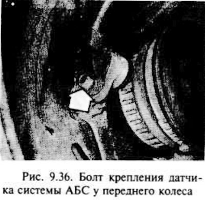
Loosen the wheel sensor bolt on the mounting bracket with a socket wrench, then carefully remove it with a screwdriver. Remove O-ring (pic. 9.36.).
Check the condition of the sealing ring and, if necessary, replace it.
Installation is carried out in the reverse order of removal, taking into account the following.
Apply a small amount of grease to the sensor body before mounting it to the bracket.
Make sure the ABS warning light turns off when the engine is first started. At the first opportunity, have the ABS system checked at a workshop using special equipment.
Rear wheel sensor
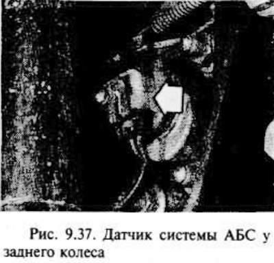
The rear wheel sensors are integral with the rear wheel hub assembly kit and cannot be separated from the hub. More about it see chapter 10 (pic. 9.37).
Electronic control unit
Make sure the ignition is off, then disconnect the negative battery terminal.
The block is connected to the hydraulic modulator assembly located in the engine compartment.
Remove the screw and plastic cover from the hydraulic modulator.
Disconnect the control unit connector and solenoid valve wires.
Remove the two relays from the top of the assembly.
Disconnect the remaining connector from the control unit.
Remove the seven screws and remove the control box from the modulator assembly.
Installation is carried out in the reverse order of removal, but try not to overtighten the screws of the control unit.
Relay
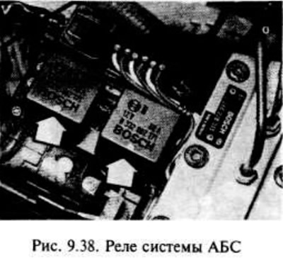
Two relays are used, one for the solenoid valve and one for the pump motor; both of them are installed on the control unit (pic. 9.38).
Disconnect the negative battery terminal.
Remove the screw and plastic cover from the hydraulic modulator.
Remove the appropriate relay.
Installation is carried out in the reverse order of removal.
Check that the ABS warning light turns off after the first start of the engine. As soon as possible, have the entire system checked in a workshop using specialized equipment.
Visitor comments