
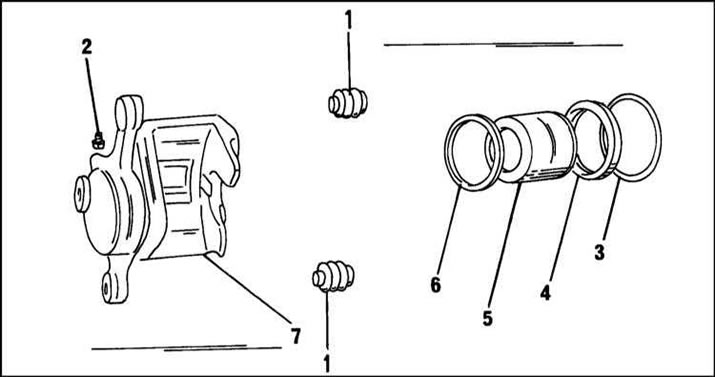
Details of the front brake caliper of a car from the middle of 1995 of release: 1 - protective cover; 2 - fitting for removing air; 3 - retaining ring; 4 - dustproof ring; 5 - piston; 6 - cuff; 7 - support
At support repair it is necessary to be guided by the instructions given in subsection 12.1.2 for a support of the car since the middle of 1995 of release.
Caliper installation
If there are any external defects in the brake hose connection seals, they should be replaced.
1. If the shoe guide has been removed, install and bolt it to the axle housing.
2. Tighten the bolts to 104 Nm.
3. Attach the brake hose to the caliper, making sure the hose is in the correct position. The guide pin must enter the caliper hole.
4. Tighten the hollow bolt for connecting the brake hose to 35 Nm.
5. Tighten the bleeder fittings to 8 Nm and close with caps.
6. Reinstall the brake pads as described above.
7. Remove the polyethylene from the filler neck of the master cylinder reservoir.
8. Add brake fluid if necessary and tighten the reservoir cap.
9. Other work is carried out in the reverse order of removal.
10. Bleed the brake system as described below.
11. After assembly, check the system for leaks.
12. Check the operation of the brake system while the vehicle is moving.
Before removing the brake disc, it must be checked for runout, as the disc may be deformed. The brake disc is attached with a Torx head bolt. However, the bolt does not fully press the disc against the wheel hub. To ensure a full fit, one of the wheel bolts is screwed with a spacer into the hub opposite the brake disc bolt and clamps the hub. In this way, uniform fastening on the right and left is achieved.
Checking the disc for runout is carried out in accordance with the description given in Section 1. Brake discs can be ground if necessary. The minimum allowable disc thickness is given in Specifications.
The brake disc is removed as follows:
1. If the wheel has already been removed, as discussed above, remove the wheel bolt used to check the runout.
2. Remove the brake disc and wire the caliper to the chassis as described in Section 2.

3. Turn out both bolts and disconnect directing from a brake disk.
4. Unscrew the fastening bolt in the end surface of the brake disc with a special key. The bolt has a head "Torx".
5. Remove the brake disc from the wheel hub. If necessary, you can use a rubber mallet for this.
Before installing the brake disc, clean the mating surfaces of the disc and wheel hub with fine emery cloth. If a new brake disc is installed, it must be cleaned of grease.
1. Install the brake disc and tap it with a rubber mallet.
2. Screw in and tighten the mounting bolt.
3. Check the brake disc for runout as described above.
4. An unexpected beating may be due to the ingress of foreign particles between the mating planes of the disc and the hub. Then disassemble the connection again, clean and reassemble.
5. Install the guide and tighten the bolts of its fastening to 104 Nm.
6. Install the brake pads as described in Section 2, respecting the torque of the guide pins. On the rear calipers, the guide pins are fastened with a torque of 44 Nm.
7. Lower the vehicle onto the wheels and tighten the wheel bolts to 110 Nm.
Attention! Light alloy wheels are fastened with a torque of 120 Nm.
Note: The thickness of the brake discs can be measured without removing them. This is done with a caliper as shown. Be aware of the difference in performance.
Visitor comments