
Note: Before disassembling the master cylinder, make sure you have the right parts on sale, and save the old components to use as a reference when buying a replacement.
1. Remove the master cylinder as described in Chapter 15.
Main cylinder type GMF
2. Clamp the master cylinder in a vice with soft jaws.
3. Where installed, unscrew the pressure control valves from the base of the cylinder.
4. Carefully remove the O-ring from the end of the cylinder using a screwdriver as a lever.
5. Lightly press the primary piston using a wooden or plastic stick. Hold the piston down by inserting a 3.0mm diameter smooth pin or rod through the feed pot primary port into the cylinder (see illustration).
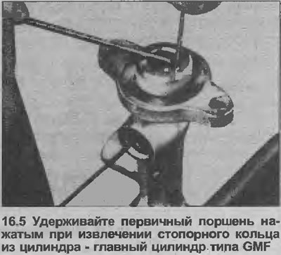
6. Remove the circlip from the end of the cylinder using a screwdriver. Do not damage the piston or cylinder walls.
7. Remove the pin or rod that secures the piston.
8. Remove the primary piston assembly from the cylinder by tapping the cylinder against a block of wood if necessary.
9. Inject low pressure air into the cylinder (e.g. with a foot pump) through the front channel of the feed pot to expel the secondary piston assembly.
10. Clean all components using only clean brake fluid or methyl alcohol and inspect them for signs of wear and damage. In particular, check the pistons and cylinder bore for scratches and corrosion. If the cylinder walls are worn, replace the master cylinder assembly (see illustration).
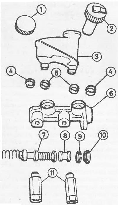
16.10 GMP Master Cylinder Components
1 Filler cap (standard)
2 Filler cap (with liquid level sensor)
3 Nutrient tank
4 Brackets for the nutrient tank
5 Feed tank seals
6 Cylinder
7 Secondary piston and springs
8 Primary piston
9 Retaining ring
10 O-ring
11 Pressure control valves
11. If the cylinder bore is in good condition, purchase a repair parts kit that will contain all the necessary replacement parts already assembled
12. Lubricate the cylinder bore with clean brake fluid or brake grease, then clamp the cylinder horizontally in a vise with soft-padded jaws.
13. Remove the plug from the end of the accessory tube (included in repair kit) and insert the short part of the tube up to the shoulder into the cylinder bore.
14. Use a block of wood or plastic to push the components out of the tube and into the bore of the cylinder. Then insert into the cylinder through the primary bore of the feed pot the pin or rod that was used in the removal to keep the primary piston depressed.
15. Insert a new circlip into the end of the cylinder bore, making sure it is seated correctly and that the piston moves freely in the cylinder.
16. Press the primary piston and remove the pin or rod from the feed pot channel.
17. Install a new O-ring on the end of the cylinder.
18. Where applicable, screw the pressure control valves into the base of the cylinder
19. Install the master cylinder as described in Chapter 15.
ATE master cylinder
20. Clamp the main cylinder in a vise with soft jaws.
21. Where applicable, unscrew the pressure control valves from the base of the cylinder.
22. Carefully remove the O-ring from the end of the cylinder using a screwdriver as a lever.
23. Lightly press the primary piston using a wooden or plastic ram, then remove the circlip from the end of the cylinder.
24. Remove the primary piston assembly, noting the location of the restrictor washers.
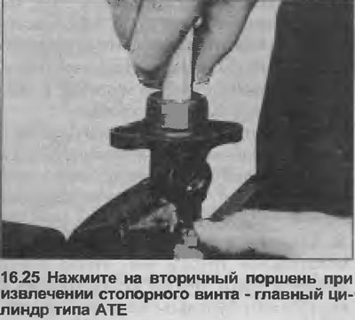
25. Press down on the secondary piston, again using a wooden or plastic ram, and remove the set screw from the cylinder body (see illustration).
26. Remove the secondary piston assembly from the cylinder, tapping the cylinder against a block of wood if necessary to force the piston out of the bore.
27. Clean all components using only clean brake fluid or methyl alcohol, and inspect them for signs of wear and damage. In particular, check the pistons and cylinder bores for scratches and corrosion. If the inner walls of the cylinder are worn, replace the master cylinder assembly (see illustration).
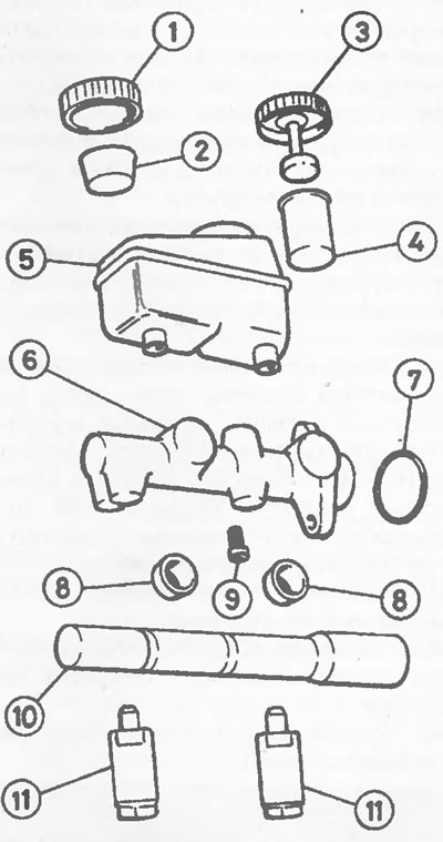
16.27 Type ATE master cylinder components
1 Filler cap (standard)
2 Strainer
3 Filler cap (with liquid level sensor)
4 Guide sleeve for float
5 Nutrient cup
6 Cylinder
7 O-ring
8 Feed tank seals
9 Locking screw
10 Repair kit accessory tube
11 Pressure control valves
28. If the cylinder walls are in good condition, purchase a repair parts kit that will contain all the necessary replacement parts already assembled.
29. Lubricate the cylinder bore with clean brake fluid or brake grease, then clamp the cylinder horizontally in a soft-jawed vise.
30. Install a new O-ring on the retaining screw, then screw the screw lightly into the cylinder body so that it does not protrude into the bore.
31. Remove the plugs from the ends of the accessory tube, then remove all components from the short section of the tube and push it into the long section of the tube until the ends are flush.
32. Insert the auxiliary tube into the cylinder bore up to the rim of the short sleeve. Then, use a wooden or plastic die to assemble the secondary piston into the cylinder.
33. Lightly tighten the lock screw, then remove the wood or plastic block and auxiliary tube, and fully tighten the lock screw.
34. Turn the main cylinder in a vise to a vertical position.
35. Lubricate the primary piston skirt and seal grooves with the special grease included in the parts repair kit. Install the restrictor washer on the piston.
36. Move the short part of the auxiliary tube so that the end of the long part of the tube is flush with the inner shoulder of the short part.
37. Install the front seal on the primary piston with the open end of the seal facing the front of the master cylinder.
38. Install an auxiliary tube on the cylinder to compress the seal, insert the end of the piston and tube into the hole and remove the tube.
39. Install the intermediate ring on the primary piston, then install the remaining seal using the auxiliary tube as described above.
40. Place the stopper washer on the primary piston, then press the piston lightly using a wood or plastic die and install a new circlip into the end of the cylinder bore. Make sure the retaining ring is installed correctly and that the piston moves freely.
41. Install a new O-ring on the edge of the cylinder.
42. Where applicable, screw the pressure control valves into the base of the cylinder.
43. Install the master cylinder as described in Chapter 15.
Visitor comments