
Brake system with new master cylinder and new brake booster
The operation of the tandem cylinder is based on the principle «plunger».
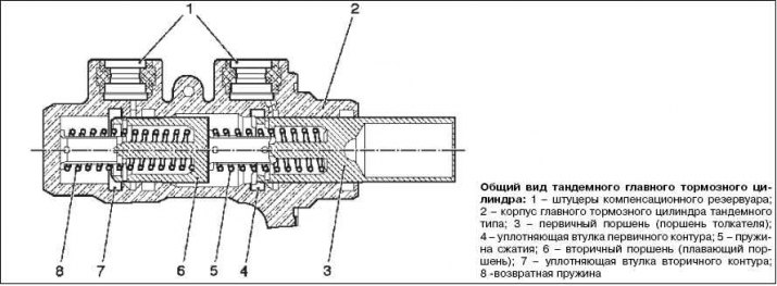
Unlike a conventional brake master cylinder, the seal bushings are built into the body instead of being mounted on the piston as before. The bore in the housing thus guides the pistons directly. This design reduces the length of the tandem brake master cylinder by 25%. In addition, the number of nodes has been reduced to 15, thus significantly reducing the weight, dimensions and maintenance time.
«Plunger» The 2nd generation tandem type brake master cylinder, like almost all brake cylinders, provides a dual-circuit brake system. The pressure circuits are arranged in series. Driver force is transmitted as usual, from the brake booster rod to the primary pistons. A pre-pressure compression spring is mounted at the end of the primary piston, and this provides a virtually simultaneous transmission of force to the secondary piston (floating piston). The combined action of the two pistons through a single spring reduces free play and causes the secondary brake circuit to respond more spontaneously than in a conventional tandem master cylinder.
In the system used to date, the secondary piston is driven by the pressure in the primary circuit of the braking system. This leads to an increase in free play, because first the pressure must rise to the set value. The second compression spring, located behind the secondary piston, is returnable. It must be hard enough to overcome the friction of the sealing bushes, but at the same time soft enough to allow compression under the action of the primary spring when the brakes are applied.
In the initial position, there is a depressurized connection between the tandem-type brake master cylinder and the compensation reservoir. This provides pressure and performance compensation in the braking system. When the brake is actuated, the cylinder pistons retract into the seal sleeve after a short free play. The connection to the non-pressurized expansion tank is then terminated. After the rubber elements have provided a seal, the volume of brake fluid begins to move and the brake system is pressurized. After the brake is released, the return spring pushes the pistons back until the depressurized connection between the tandem brake master cylinder and the compensation reservoir is restored.
In vehicles equipped with ESP or traction control, the performance of the brake system in the event of system intervention must be provided with an additional supply. Since the time to reach the operating mode of the ABS pump depends on the suction resistance in the system, the cross-sections of the holes and channels should be as large as possible.
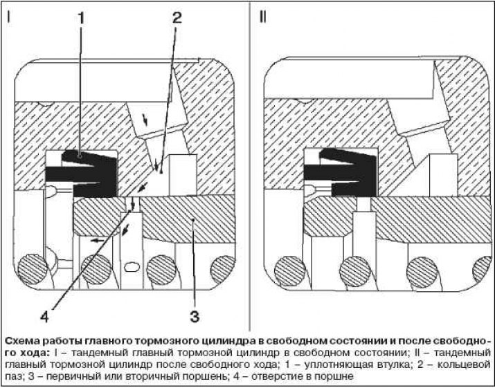
In the event of intervention by the traction control system, the performance of the brake system is provided by an annular groove that is located opposite the hole in the piston when the brake master cylinder is in a free state. When the brakes are activated during control, the extra brake fluid that was supplied to the brakes by the traction control system is returned back to the pressure compensation reservoir. The rate of return pressure build-up is determined by the instantaneous braking performance and the brake system pressure that has been generated by the traction control system.
If, when applying the brakes, the control system changes from traction control to anti-lock brake application, the compensation port may open under pressure in the master cylinder as a result of the need to return brake fluid to the master cylinder during the depressurization phase of the anti-lock brake system. The outflow pressure to the compensation tank depends only on the pressure in the master cylinder, which is controlled by the driver. The amount of fluid that flows back into the reservoir at this time depends essentially on the performance of the braking system and the current control parameters.
A combination of load, overflow and exhaust during brake operation is possible as a system state.
The primary sleeve of the tandem type brake master cylinder remains pressurized by excess capacity in the brake circuit until the end position is reached.
The inner lip of the primary bushing is pressurized on both the outside and the piston side to compensate for the full pressure on the bushing. This prevents damage to the edge of the sleeve (sealing edge) when the piston is out of range, as is the case in a tandem master cylinder with a compensation hole, where the pressure drop across the sleeve takes place.
Basically a change due to backfilling (derating at constant pressure) is the same as the change when the pedal is released (decrease in pressure with a decrease in productivity), since the edge of the sleeve is in contact with the piston when performance decreases.
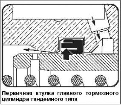
In the case of the ESP system, however, brake fluid must also be supplied whenever the brake master cylinder is actuated. In this case, the anti-lock brake system pump supplies additional brake fluid from the compensation reservoir. The brake fluid then flows through the primary sleeve, causing the sealing lip to collapse, creating an annular gap between the piston and the bore. Brake fluid can now reach the appropriate supply port.
Arrows indicate the direction of the brake fluid flow.
Position arrow - the outer edge of the sealing sleeve is bent inward.
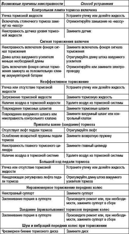
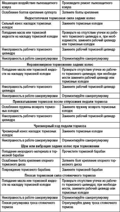
Possible malfunctions, their causes and remedies
Loop fault
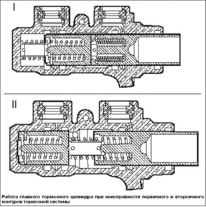
If the brake circuit fails, the free play increases. In case of failure of the primary circuit, the primary piston rests on the secondary piston, and the brake booster rod sets the latter in motion due to mechanical connection (I).
In case of failure of the secondary circuit, the secondary piston rests against the limiter at the end of the cylinder bore, after which the pressure in the primary circuit rises (II).
Visitor comments