OpelBook.ru
Cars AvtoVAZ Cars Mitsubishi Cars BMW Cars Mercedes Cars Nissan Cars Toyota Cars Chevrolet
English Русский
Български
Беларускі
Український
Српски
Hrvatski
Română
Polski
Slovenský
Magyar
 |  Sitemap  |  Contacts  |    


Main Astra Corsa Insignia Kadett Omega Vectra Zafira Others Articles
Frontera A (1991-1998, petrol) Frontera B (1998-2004) Ascona C (1981-1988) Vivaro A (2001-2014)
  • Main
  • Opel
  • Frontera B
  • Transmission
  • Automatic gearbox 4L30E
  • Removal and installation the gearbox together with the transfer case

Removal and installation the gearbox together with the transfer case (Opel Frontera B)

            0

Contents: Removal ⬇ Installation ⬇
Warning! Before removing the transmission together with the transfer case from the vehicle, use the switch located on the instrument panel to switch the transfer case from 2WD mode to 4WD mode.
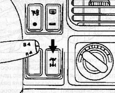

Warning! Before removing the transmission together with the transfer case from the vehicle, use the…


Removal


Disconnect the cable from the negative battery terminal.

Remove the gearshift lever (see the relevant chapter).
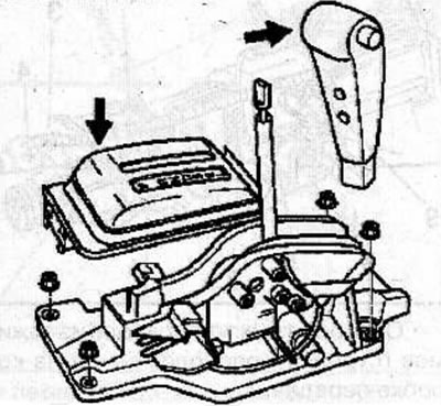
Remove the gearshift lever (see the relevant chapter).


Remove the transfer case control lever (see the relevant chapter).

Raise the car.

Remove the gearbox guard (1) and plate (3).
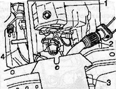
Remove the gearbox guard (1) and plate (3).


Remove the front exhaust pipes (2 and 4) (the picture shows the 6VD1-W engine).


Mark the relative positions of the propeller shaft flanges and drive flanges on the front and rear axles, then remove the propeller shafts.

Disconnect the fuel lines from the clamps located on the side of the transmission housing.
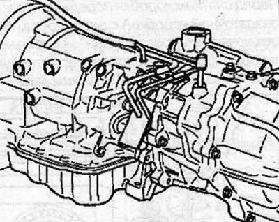
Disconnect the fuel lines from the clamps located on the side of the transmission housing.


Disconnect the wiring harness connectors from the oxygen concentration sensor (1 and 9, only on vehicles with 6VD1-W engine), transfer case switch (2), speed sensor (3), 4WD drive (4), magnetic sensor (5), main connector (6), transfer case mode switch (7) and case adapter (8).
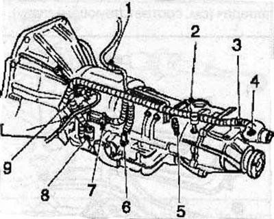
Disconnect the wiring harness connectors from the oxygen concentration sensor (1 and 9, only on…


Release the wire harness from the clamps (arrows) located on the gearbox.
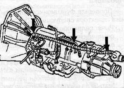
Release the wire harness from the clamps (arrows) located on the gearbox.


On a vehicle with a 6VD1-W engine, remove the bolts and heat shield from the wiring harness.
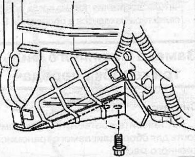


On a vehicle with a 6VD1-W engine, remove the bolts and heat shield from the wiring harness.


Use a jack to support the gearbox through a wooden block.

Loosen the nuts securing the gearbox support to the rear beam.
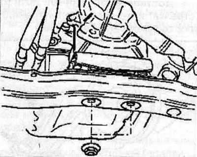
Loosen the nuts securing the gearbox support to the rear beam.


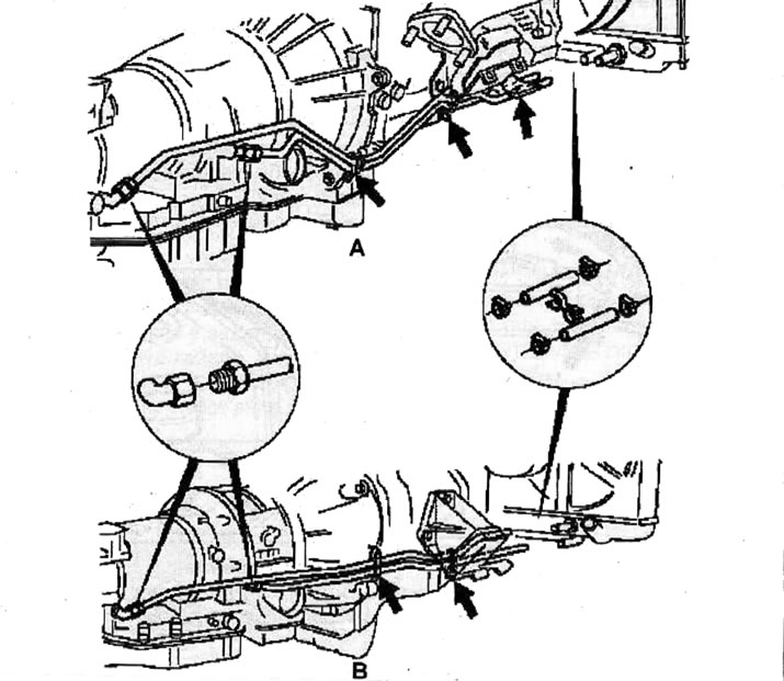
Loosen the nuts that connect the transmission fluid tubes that connect the gearbox to the heat exchanger, release the tubes from the clamps, loosen the clamps, disconnect the tubes from the hoses and remove the tubes from the vehicle.
Location of transmission fluid tubes connecting the gearbox to the heat exchanger:A - car with…

Location of transmission fluid tubes connecting the gearbox to the heat exchanger:A - car with 6VD1-W engine; B - car with X 22 DTH engine.


Note: To prevent dirt and dust from entering the gearbox, close the pipes and hoses with suitable plugs.


Disconnect the transmission control cable from the transmission.
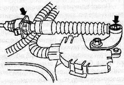
Disconnect the transmission control cable from the transmission.


Remove the starter (see the relevant chapter).

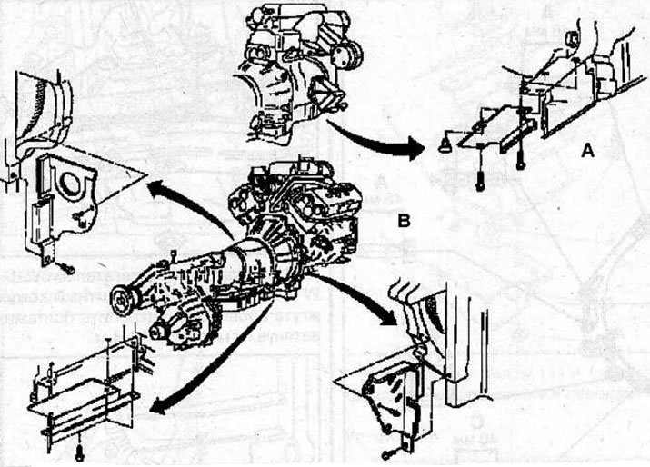
Remove the inspection covers from the clutch housing and engine.
Location of inspection covers: A - car with X 22 DTH engine; B - car with 6VD1-W engine.

Location of inspection covers: A - car with X 22 DTH engine; B - car with 6VD1-W engine.


Through the hole for installing the starter, unscrew the torque converter mounting bolts, while turning the engine crankshaft to consistently access the bolts.
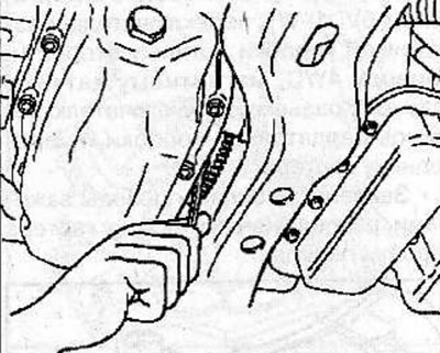
Through the hole for installing the starter, unscrew the torque converter mounting bolts, while…


Remove the bolts securing the gearbox to the engine.


Lift the transmission away from the engine, then slowly lower and remove the transmission from under the vehicle.

Warning! When removing the gearbox, do not damage nearby components or the vehicle body.


Installation


Clean the mating surfaces of the gearbox housing and engine.

Before installing the gearbox, lubricate the coupling sleeve (arrow) with lithium-based grease.
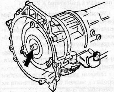
Before installing the gearbox, lubricate the coupling sleeve (arrow) with lithium-based grease.


Use a jack to raise the transmission so that the front of the transmission is aligned with the rear of the engine.

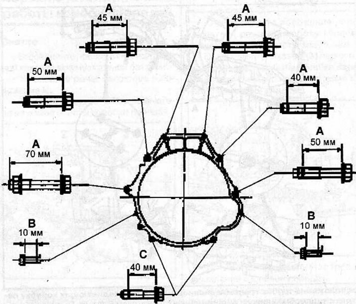
Tighten the transmission-to-engine mounting bolts as follows:
  • bolts A: 76 Nm
  • bolts B: 8 Nm
  • bolts C: 40 Nm

Location of the gearbox mounting bolts to the 6VD1-W engine.
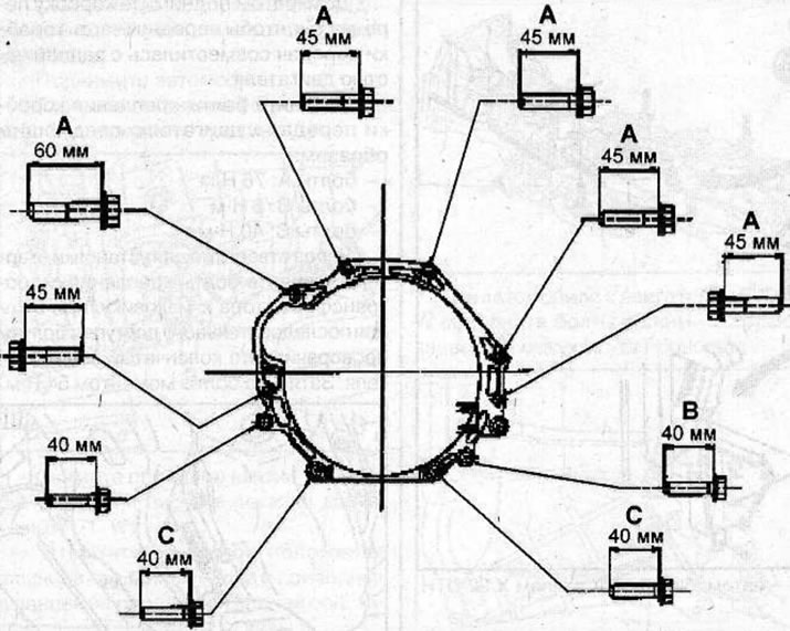
Location of the gearbox mounting bolts to the 6VD1-W engine.


Location of gearbox mounting bolts to engine X 22 DTH.

Location of gearbox mounting bolts to engine X 22 DTH.


Through the hole for installing the starter, screw in the bolts securing the torque converter to the flywheel, while turning the engine crankshaft to consistently access the bolts. Tighten the bolts to 54 Nm.
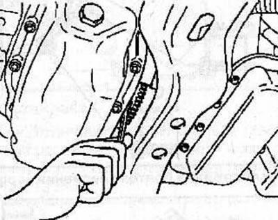
Through the hole for installing the starter, screw in the bolts securing the torque converter to…


Install the inspection covers on the clutch and engine housings and secure with bolts, tightening them to a torque of 8 Nm.

Install the starter (see the relevant chapter).

Connect the transmission control cable to the transmission (see the relevant chapter).
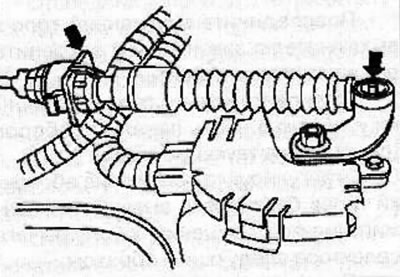
Connect the transmission control cable to the transmission (see the relevant chapter).


Install and connect the transmission fluid tubes connecting the transmission to the heat exchanger. Tighten the pipe union nuts to 44 Nm.
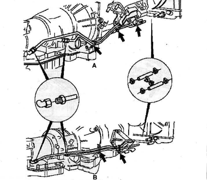
Location of transmission fluid tubes connecting the gearbox to the heat exchanger: A - car with…

Location of transmission fluid tubes connecting the gearbox to the heat exchanger: A - car with 6VD1-W engine; B - car with X 22 DTH engine.


Install the rear beam on the vehicle chassis and secure with bolts, tightening them to a torque of 76 Nm.

Use nuts to secure the gearbox support to the rear beam and tighten them to a torque of 50 Nm.
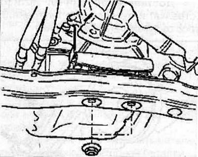
Use nuts to secure the gearbox support to the rear beam and tighten them to a torque of 50 Nm.


On a vehicle with a 6VD1-W engine, install the heat shield for the wiring harness and secure with bolts, tightening them to a torque of 8 Nm.
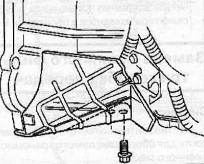
On a vehicle with a 6VD1-W engine, install the heat shield for the wiring harness and secure with…


Secure the wiring harness with the clamps located on the gearbox.

Connect the wire harness connectors to the oxygen sensor (only on vehicles with 6VD1-W engine), transfer case switch, speed sensor, 4WD drive, magnetic sensor, main connector, transfer case mode switch and case adapter.

Secure the fuel lines with the clamps located on the side of the gearbox housing.
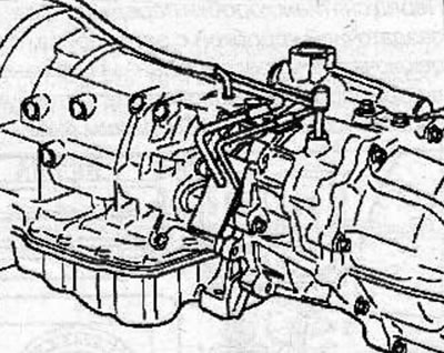


Secure the fuel lines with the clamps located on the side of the gearbox housing.


Install the front exhaust pipes (2 and 4) (the picture shows the 6VD1-W engine).

Install the gearbox guard (1) and plate (3).

Align the previously applied marks and connect the rear propeller shaft flanges to the gearbox and rear axle and secure them with bolts and nuts, tightening them to a torque of 63 N·m.
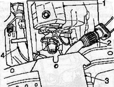
Align the previously applied marks and connect the rear propeller shaft flanges to the gearbox and…


Install the transfer case control lever (see the relevant chapter).
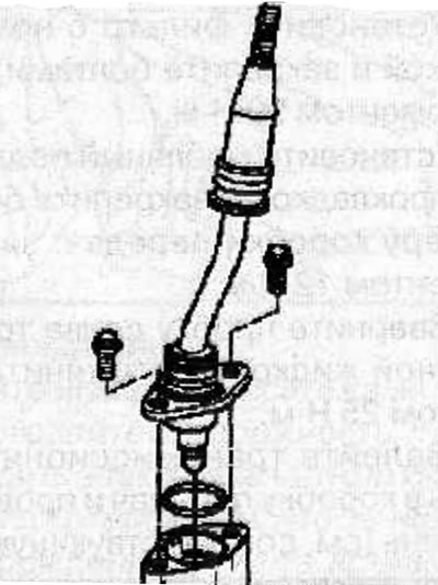
Install the transfer case control lever (see the relevant chapter).


Install the gearshift lever (see the relevant chapter).
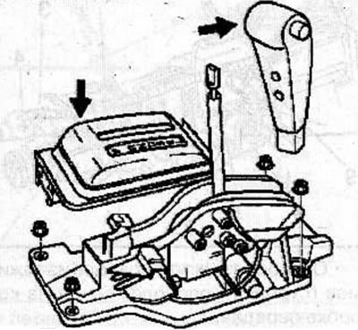
Install the gearshift lever (see the relevant chapter).


Connect the cable to the negative terminal of the battery.


This article is available at russian, bulgarian, belarusian, ukrainian, serbian, croatian, romanian, polish, slovak, hungarian
Checking the article: Chernov Alexander

Share information:

Previous articles
Opel Frontera B: Automatic gearbox 4L30E
Next articles

Replacing the gearbox oil filter
Ignition Switch Lock Cable
Gearbox control cable
Selector lever
Adjusting the band brakes
Adjusting the position of the gearbox mode switch
Transmission support
Gearbox operating mode switch
Replacing the oil pan gasket
Electrical connectors for solenoid valves
Gearbox housing solenoid valves
Transition Crankcase Solenoid Valves


See similar ones from other Opel car manuals:
▶ Transfer case replacement Opel Insignia A (2008-2017)
▶ Checking the level and adding oil to the transfer case Opel Vectra A (1988-1995)
▶ Gearbox Oil — Draining and Filling Opel Astra F (1991-1998, petrol)
▶ Easytronic gearbox Opel Corsa C (2000-2006, petrol)
▶ Removal and installation the gearbox Opel Kadett E (1984-1995)
Link to this page in different formats

Visitor comments


No comments yet


How much will 41 + 48 =


Vivaro A (2001-2014) 
  • General information
  • User manual
  • Power unit
  • Petrol engine F4R
  • Diesel engine F9Q
  • Diesel engine G9U
  • Transmission
  • Clutch and drive shafts
  • Manual gearbox
  • Chassis
  • Front suspension
  • Rear suspension
  • Brake system
  • Body
  • Exterior
  • Interior
  • Electrical equipment
  • Heating and ventilation
  • Air conditioner
  • Equipment and devices
  • Electrical diagrams
Ascona C (1981-1988) 
  • General information
  • Maintenance
  • Power unit
  • Gasoline engines
  • Diesel engines
  • Cooling system
  • Fuel and exhaust system
  • Contact ignition system
  • Contactless ignition system
  • Transmission
  • Clutch
  • Mechanical gearbox
  • Automatic gearbox
  • Drive shafts
  • Chassis
  • Steering
  • Brake system
  • Car suspension
  • Body
  • Exterior
  • Interior
  • Doors and windows
  • Electrical equipment
  • Equipment and devices
  • Power devices
  • Electrical circuits
Frontera B (1998-2004) 
  • General information
  • User manual
  • Maintenance
  • Power unit
  • Petrol engines 2.2 l
  • Petrol engines 3.2 l
  • Diesel engines 2.2 l
  • Cooling system
  • Fuel system (petrol)
  • Fuel system (diesel)
  • Ignition system
  • Transmission
  • Clutch
  • Manual gearbox MUA5C
  • Automatic gearbox 4L30E
  • Chassis
  • Suspension and axles
  • Steering
  • Brake system
  • Body
  • Exterior
  • Interior
  • Doors, locks and windows
  • Heating and air conditioning
  • Electrical equipment
  • Power devices
  • Equipment and devices
  • Lighting and signaling
  • Electrical diagrams
Frontera A (1991-1998, petrol) 
  • General information
  • Introduction to guide
  • User manual
  • Maintenance
  • Power unit
  • Engine repair
  • Lubrication system
  • Cooling system
  • Power and exhaust system
  • Engine electrics
  • Transmission
  • Clutch
  • Mechanical gearbox
  • Cardan shafts
  • Chassis
  • Brake system
  • Front suspension
  • Rear suspension
  • Steering
  • Body
  • Repair and care
  • Electrical equipment
  • Equipment and devices
  • Electrical circuits
OpelBook.ru © 2017–2026 · Mobile version · · Sitemap: EN BG BY UA RS HR RO PL SK HU · Feedback · Site search
Astra F, petrol · Astra G, petrol · Astra G · Astra H · Astra J, petrol · Corsa B · Corsa C, petrol · Corsa C · Insignia A · Kadett D · Kadett E · Omega A · Omega B · Omega B2 · Vectra A, petrol · Vectra A · Vectra B, petrol · Vectra B · Vectra C · Zafira A, petrol · Frontera A, petrol · Frontera B · Ascona C · Vivaro A ·
We want your visit to be comfortable 🤝! We use cookies 🍪 to make that happen.