
Note: This is a complex procedure, it is recommended that you read the Chapter carefully before starting work. When assembling, various components need to be replaced, purchase replacements in advance. In addition, you will need equipment to support the engine during the procedure and a special tool to insert the transmission input shaft into the clutch assembly during installation.
Removing
1. Disconnect the negative cable from the battery.
2. Working in the engine compartment, loosen the pinch bolt securing the gear selector rod to the linkage. Slide the selector rod against the bulkhead of the engine compartment to separate it from the linkage.
3. Remove the mounting bracket, then separate the clutch cable from the release lever by pulling the lever back against the bulkhead. Pull the cable holder away from the bracket on the transmission housing, then move the cable to the side, noting its correct location.
4. Disconnect the wiring from the reversing light switch located on the front side of the transmission case, above the left mounting bracket.
5. Unscrew the mounting sleeve and disconnect the speedometer drive cable from the transmission.
6. Unscrew and remove the top three bolts securing the transmission to the engine.
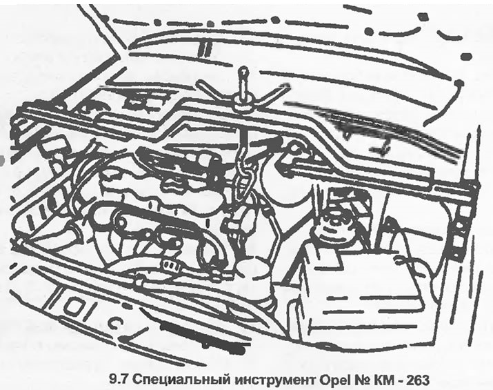
7. The engine should now be supported near its left bracket. Ideally, this should use a strong wooden or metal beam, installed securely in the recesses of the upper edges of the wing panels. An Opel tool specially designed for this purpose is shown in Figure 9.7. Alternatively, the engine can be supported with a winch and hoist. However, in this case, the design of the winch must allow the engine to be supported on a jacked up vehicle.
8. Where applicable, remove the caps, then loosen the front wheel bolts. Apply the handbrake, then jack up and support the front of the vehicle on axle stands. Please note that the vehicle must be raised high enough so that the transmission can be removed from under it. Remove the front wheels.
9. Make sure the engine is supported securely, then remove the subframe as described in Section 10.
10. Disconnect the inner ends of the drive shafts from the differential (see Section 8). Be prepared for oil to escape and seal the openings in the differential to prevent further oil loss and dirt from entering the system. Tie the drive shafts to the body with wire or twine, do not let them hang under their own weight.
11. Loosen the mounting nut and disconnect the ground strap from the transmission end plate.
12. Place a container under the transmission end plate to catch the oil, then unscrew the mounting bolts and remove the plate. Note the location of the bolt securing the ground strap. To improve access, remove the wheel arch insert as described in Section 11.
13. Remove the gasket.
14. Remove the retaining ring from the inner end of the input shaft using special pliers.
15. Remove the socket head screw from the end of the input shaft.
16. Remove the input shaft from the clutch friction disc hub as described in Section 6. There is no need to remove the clutch assembly unless replacement of its components is required.
17. Support the transmission with a jack, laying a piece of board between them.
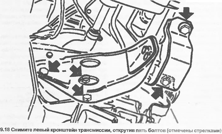
18. Remove the left transmission bracket by unscrewing the two bolts securing the rubber pad to the vehicle body and the three bolts securing the mounting bracket to the transmission (see illustration).
19. Unscrew the mounting bolts and remove the protective cover from the base of the clutch housing.
20. Make sure the transmission is supported securely, then loosen and remove the remaining transmission-to-engine bolts.
21. Lower the transmission and remove it from under the front of the vehicle.
The help of an assistant will greatly facilitate the work.
Installation
22. Before starting installation, make sure that the two bolts that you removed from the left transmission bracket to the body rotate freely in the corresponding threaded holes in the body. If necessary, regrind the threaded holes using a M10x1.25 mm tap.
23. On models equipped with "flat" (not cupped flywheel (see Section 6), it will be easier to assemble the clutch after installing the transmission.
24. Position the transmission under the front of the vehicle by jacking it up and running a piece of wood between them.
25. Raise the transmission just enough to install the lower transmission-to-engine bolts, thread the bolts but do not fully tighten them at this stage.
26. Install the left transmission bracket using two new bolts to secure the rubber pad to the vehicle body. Tighten all bolts with a tightening torque specified specifications.
27. Tighten the lower transmission-to-engine mounting bolts installed earlier with the tightening torque specified in the Specifications, then remove the jack from under the transmission.
28. Where it was removed, install the clutch. Insert the transmission input shaft into the clutch friction disc hub as described in section 6.
29. Install a socket head cap screw into the end of the input shaft, then install a new circlip.
30. Using a new gasket, install the transmission end plate and tighten the mounting bolts with a torque specified specifications. Make sure the bolt that secures the ground strap is in the correct location marked during removal,
31. Place the transmission ground strap on the bolt and install the mounting nut.
32. Install the protective cover on the base of the clutch housing and tighten the mounting bolts.
33. Insert the inner ends of the drive shafts into the differential (see Section 8), using new circlips.
34. Install the subframe as described in Section 10.
35. Install the front wheels, but do not completely tighten the wheel bolts at this stage.
36. If a winch and hoist were used, disconnect the hoist or lower the winch enough to allow the vehicle to be lowered.
37. Lower the vehicle to the ground, then tighten the wheel bolts to the specified torque specifications and install caps (where applicable).
38. Remove engine support equipment (if not already done).
39. Install the three upper bolts of the transmission to the engine and tighten them with a tightening torque regulated specifications.
40. Connect the speedometer drive cable and clamp the mounting sleeve.
41. Connect the electrical wiring of the reversing light switch.
42. Install the clutch cable holder to the bracket on the transmission case, then connect the cable to the release lever and adjust the length of the cable as described in Section 6. Make sure the cable is routed as noted when removed.
43. Connect the gear selector rod to the link, then adjust the link as described in Chapter 2. Tighten the pinch bolt.
44. Top up the gear oil level as described in Section 1.
45. Connect the negative cable to the battery.
Visitor comments