
OpelBook.ru
Cars AvtoVAZ Cars Mitsubishi Cars BMW Cars Mercedes Cars Nissan Cars Toyota Cars Chevrolet
English Русский
Български
Беларускі
Український
Српски
Hrvatski
Română
Polski
Slovenský
Magyar
 |  Sitemap  |  Contacts  |    


Main Astra Corsa Insignia Kadett Omega Vectra Zafira Others Articles
Frontera A (1991-1998, petrol) Frontera B (1998-2004) Ascona C (1981-1988) Vivaro A (2001-2014)
  • Main
  • Opel
  • Ascona C
  • Chassis
  • Brake system
  • Master Cylinder (ATE Type) — Inspection and Repair

Master Cylinder (ATE Type) — Inspection and Repair (Opel Ascona C)

            0

Contents: Procedures for working with a set of…⬇ Procedures for working with a set of…⬇
There are two types of repair kits available for repairing the master cylinder assembly. One is a kit with "loose" seals, and the other, newer kit, is a kit that includes a secondary piston already assembled in a special tube that is used to install the piston. Proceed according to what type of set you have.

1. After removing the unit from the machine, clean off any external dirt.

2. Remove the fluid reservoir from the cylinder body.

3. Remove the snap ring from the end of the cylinder housing. To do this, it is necessary to press lightly on the primary piston using a rod in order to relieve the tension of the spring ring.

4. Remove the primary piston, paying attention to how the seals are installed.

5. Insert the rod and push the secondary piston so that the lock screw can be removed from the cylinder body (Figure 9.33).
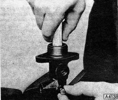
Figure 9.33 - Pressing on the secondary piston of the master cylinder (ATE)

Figure 9.33 - Pressing on the secondary piston of the master cylinder (ATE)


6. Remove the secondary piston by tapping the end of the cylinder on a wooden block. Pay attention to how the seals are installed.


7. Inspect the piston surfaces and cylinder bore for rust, scratches, or metal-to-metal friction. If this is the case, replace the entire master cylinder.

8. If the components are in good condition, clean them in hydraulic fluid or methylated spirits - and nothing else.

9. Get a repair kit that contains all the necessary spare parts.

Procedures for working with a set of "free" seals.


10. Install new seals on the pistons, using only your fingers to push them into place. It is important that the new seals are installed in exactly the same way as the old ones; they are cone shaped and will only function properly if installed in the correct order.

11. Assembly is carried out in reverse order. Be extremely careful when driving the pistons into the cylinder bores to avoid cutting the seal lips. Before assembly, soak each component in clean hydraulic fluid. Always install a new snap ring from the repair kit.

12. Install new rubber sealing rings and place the fluid reservoir in its place on the cylinder body.

13. Pour some clean fluid into the reservoir and prepare the master cylinder for operation before installation by pressing the primary piston several times with a rod. Naturally, a large amount of liquid will be ejected from the open ports of the cylinder.

Procedures for working with a set of ready-made assembly.


14. Lubricate the cylinder with brake fluid.

15. Clamp the cylinder in a vice with soft jaws so that the barrel is more or less horizontal. Tighten the locking screw slightly, but not so far that it protrudes into the barrel.


16. Remove the large plug from the tube. Remove all components from the short section of the tube and push the short section into the long section until they are flush.

17. Insert the tube into the cylinder barrel up to the flange on the short cuff. Using a blunt rod, push the secondary piston into the barrel until it reaches the end of the cylinder. Tighten the lock screw, remove the rod and collar, and fully tighten the lock screw.

18. Change the position of the master cylinder in the vice so that the barrel opening faces upward.

19. Lubricate the primary piston skirt and seal grooves with the special grease included in the repair kit. Install the retaining gasket onto the piston.

20. Adjust the tube so that the end of its long section is flush with the inner flange of the short section.

21. Install the front oil seal onto the primary piston with the open end of the oil seal facing the front of the master cylinder. Place the tube over the cylinder to compress the seal, insert the piston and tube into the barrel some distance and remove the tube.

22. Place the middle ring on the piston, then install the other seal using the tube in a similar manner.

23. Place the end gasket on the primary piston, then press the piston lightly and install the snap ring. Make sure the snap ring is in place and that the piston can move freely.

24. Install new sealing rings and put the fluid reservoir back in place.

25. Prepare the cylinder for operation by pouring clean brake fluid into the reservoir and pressing on the pistons with a rod so that fluid flows out of all the holes.
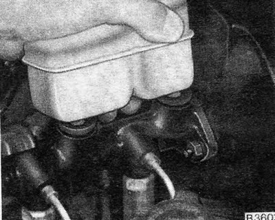


Figure 9.30 - Removing the reservoir from the ATE type master cylinder
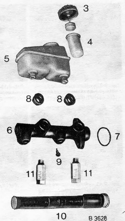
Figure 9.30 - Removing the reservoir from the ATE type master cylinder


Figure 9.31 - Disassembled ATE type master cylinder
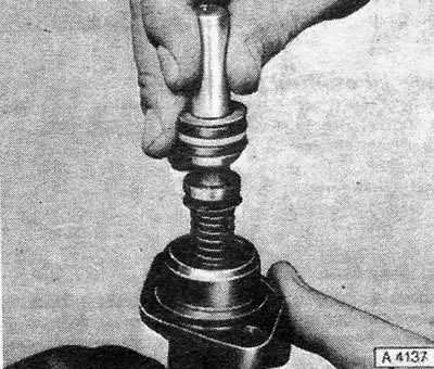
Figure 9.31 - Disassembled ATE type master cylinder


Figure 9.32 - Removing the primary piston of the master cylinder (ATE)
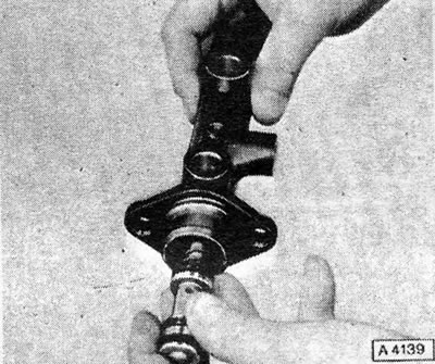
Figure 9.32 - Removing the primary piston of the master cylinder (ATE)


Figure 9.34 - Removing the secondary piston (ATE)
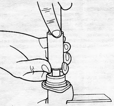
Figure 9.34 - Removing the secondary piston (ATE)


Figure 9.35 - Using the Primary Piston Assembly (ATE) Installation Tube

Figure 9.35 - Using the Primary Piston Assembly (ATE) Installation Tube


This article is available at russian, bulgarian, belarusian, ukrainian, serbian, croatian, romanian, polish, slovak, hungarian
Checking the article: Kornev Georgy

Share information:

Previous articles
Opel Ascona C: Brake system
Next articles

Master Brake Cylinder — Removal and Installation
Brake Drum — Inspection and Renewal
Rear Brake Plate — Removal and Installation
Rear Brake Cylinder — Removal, Inspection and Installation
Self-adjusting rear brakes — inspection and replacement
Self-adjusting rear brakes — description
Master Cylinder (GNF Type) — Inspection
Pressure Regulating Valves
Flexible Hoses and Rigid Tubes — Inspection and Replacement
Hydraulic system — blowing
Vacuum Servo Hose — Replacement
Vacuum servo unit (booster) — checking the operation


See similar ones from other Opel car manuals:
▶ Master Brake Cylinder — Removal, Repair and Installation Opel Astra F (1991-1998, petrol)
▶ Master brake cylinder Opel Corsa C (2000-2006, petrol)
▶ Replacing the clutch master cylinder Opel Insignia A (2008-2017)
▶ Removal and installation the brake master cylinder Opel Kadett E (1984-1995)
▶ Master Cylinder — Removal, Adjustment and Installation Opel Omega A (1986-1993)
Link to this page in different formats

Visitor comments


No comments yet


How much will 44 + 22 =


Vivaro A (2001-2014) 
  • General information
  • User manual
  • Power unit
  • Petrol engine F4R
  • Diesel engine F9Q
  • Diesel engine G9U
  • Transmission
  • Clutch and drive shafts
  • Manual gearbox
  • Chassis
  • Front suspension
  • Rear suspension
  • Brake system
  • Body
  • Exterior
  • Interior
  • Electrical equipment
  • Heating and ventilation
  • Air conditioner
  • Equipment and devices
  • Electrical diagrams
Ascona C (1981-1988) 
  • General information
  • Maintenance
  • Power unit
  • Gasoline engines
  • Diesel engines
  • Cooling system
  • Fuel and exhaust system
  • Contact ignition system
  • Contactless ignition system
  • Transmission
  • Clutch
  • Mechanical gearbox
  • Automatic gearbox
  • Drive shafts
  • Chassis
  • Steering
  • Brake system
  • Car suspension
  • Body
  • Exterior
  • Interior
  • Doors and windows
  • Electrical equipment
  • Equipment and devices
  • Power devices
  • Electrical circuits
Frontera B (1998-2004) 
  • General information
  • User manual
  • Maintenance
  • Power unit
  • Petrol engines 2.2 l
  • Petrol engines 3.2 l
  • Diesel engines 2.2 l
  • Cooling system
  • Fuel system (petrol)
  • Fuel system (diesel)
  • Ignition system
  • Transmission
  • Clutch
  • Manual gearbox MUA5C
  • Automatic gearbox 4L30E
  • Chassis
  • Suspension and axles
  • Steering
  • Brake system
  • Body
  • Exterior
  • Interior
  • Doors, locks and windows
  • Heating and air conditioning
  • Electrical equipment
  • Power devices
  • Equipment and devices
  • Lighting and signaling
  • Electrical diagrams
Frontera A (1991-1998, petrol) 
  • General information
  • Introduction to guide
  • User manual
  • Maintenance
  • Power unit
  • Engine repair
  • Lubrication system
  • Cooling system
  • Power and exhaust system
  • Engine electrics
  • Transmission
  • Clutch
  • Mechanical gearbox
  • Cardan shafts
  • Chassis
  • Brake system
  • Front suspension
  • Rear suspension
  • Steering
  • Body
  • Repair and care
  • Electrical equipment
  • Equipment and devices
  • Electrical circuits
OpelBook.ru © 2017–2026 · Mobile version · · Sitemap: EN BG BY UA RS HR RO PL SK HU · Feedback · Site search
Astra F, petrol · Astra G, petrol · Astra G · Astra H · Astra J, petrol · Corsa B · Corsa C, petrol · Corsa C · Insignia A · Kadett D · Kadett E · Omega A · Omega B · Omega B2 · Vectra A, petrol · Vectra A · Vectra B, petrol · Vectra B · Vectra C · Zafira A, petrol · Frontera A, petrol · Frontera B · Ascona C · Vivaro A ·
We want your visit to be comfortable 🤝! We use cookies 🍪 to make that happen.