
Models manufactured before 1985.
1. Remove the air cleaner from the carburetor along with the tubes and hoses.
2. Disconnect the vacuum hose from the intake manifold by unscrewing the coupling nut.
3. Disconnect the vacuum hose from the servo assembly.
4. Disconnect the low level warning light switch wire located on the master cylinder fluid reservoir.
5. Unscrew the master cylinder from the servo assembly.
6. Carefully pull the master cylinder off the servo assembly as far as the flexibility of the hydraulic tubes will allow.
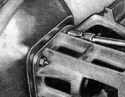
7. Working from inside the vehicle, remove the cover located under the instrument panel to gain access to the remote control caliper mounting nuts and bolt located on the inside surface of the bulkhead (Pic. 9.46).
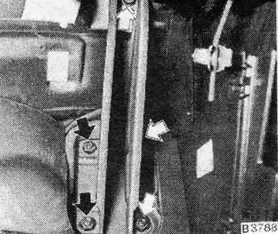
Pic. 9.46 - Mounting nuts and bolts of the remote control support - indicated by arrows
8. Unscrew and remove the nuts and bolt.
9. Disconnect the brake pedal return spring.
10. Remove the spring ring from the bracket stud on the brake pedal lever, press out the pin to release the pedal lever from under the push rod of the servo assembly.
11. Still working from the dashboard side, remove the nuts that secure the brake pedal support bracket (Pic. 9.47).
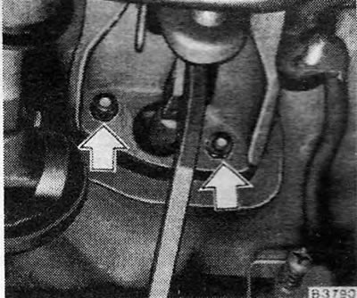
Pic. 9.47 — The nuts of the brake pedal support bracket are indicated by arrows
12. Working from the engine compartment side, remove the servo assembly and brake remote control assembly from the bulkhead (Pic. 9.48).
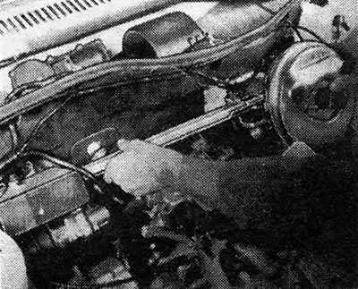
Pic. 9.48 — Removing the remote control and servo assembly from the partition
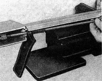
13. Secure the remote control rod support in a vice.
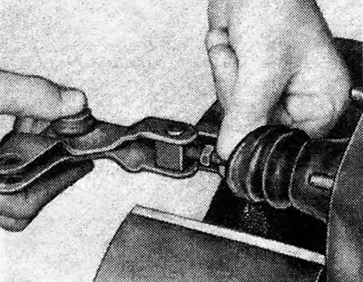
14. Move the spring leg of the crank lever (Pic. 9.49). Then remove the snap ring and remove the spring (Pic. 9.50).
Pic. 9.49 — Releasing the crank arm spring leg
Pic. 9.50 — Removing the spring circlip
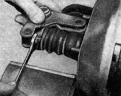
15. Tap to remove the locking pin that holds the crank pin in place (Pic. 9.51).
Pic. 9.51 — Remove the crank arm pin locking pin
16. Remove the crank pin.
17. Remove the snap ring from the remote control king pin.
18. Remove the kingpin to disengage the remote control assembly from the bell crank on the servo assembly (Pic. 9.53).
Pic. 9.53 — Removing the kingpin from the servo unit
19. Unscrew the mounting nuts and disconnect the servo assembly from the remote control rod support (Pic. 9.54).
Pic. 9.54 — Removing the servo assembly mounting nuts
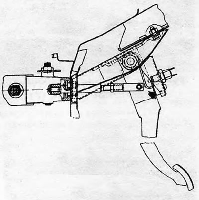
20. Support the servo assembly and unscrew the nut from the crank arm support (Pic. 9.55).
Pic. 9.55 — Nut of the crank arm of the servo unit
21. Remove the crank arm by unscrewing it from the servo push rod.
22. Reassemble in the reverse order, just lubricate the crank arm pins with grease and perform the following adjustments. All nuts and bolts must be tightened to the specified torque values.
23. Pull the remote control rod towards the brake servo assembly. Measure the lengths (A) protruding threads on the rod as indicated (see Fig. 9.57).
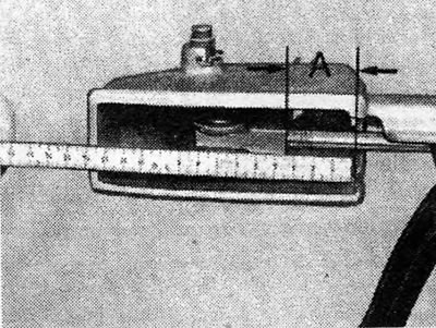
Pic. 9.57 — Measuring diagram of the thread of the remote control rod A= from 28.5 to 29.5 mm (from 1.12 to 1.16 d).
24. If adjustment is required, loosen the lock nut of the remote control rod and rotate the rod. Once adjusted, install the boot on the front of the king pin case.
25. With the assembly in place on the bulkhead, climb inside the car and loosen the pedal pushrod lock nut.
26. Connect the push rod bracket fork to the brake pedal lever.
27. Rotate the push rod until the pedal arm rests on the rubber stop. Tighten the push rod lock nut and then install the pedal return spring.
28. Install the master cylinder to the servo assembly and connect the vacuum hose and low fluid warning light.
Models manufactured after 1985.
29. Since 1985, the servo assembly and master cylinder are mounted on the right side of the bulkhead. To remove the servo assembly, proceed as follows.
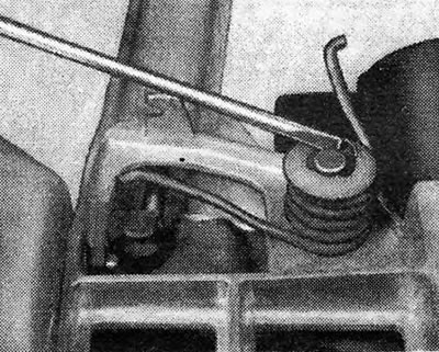
30. Remove the air cleaner if necessary for easier access and disconnect the vacuum hose from the servo assembly (photo).
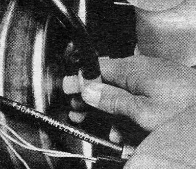
Photo 23.30 Disconnecting the servo vacuum hose (models after 1985)
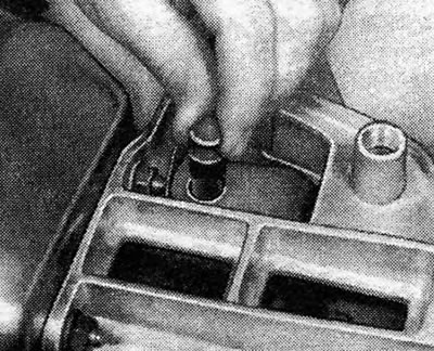
31. Remove the two nuts that secure the master cylinder to the servo assembly. Disconnect the wires from the fluid warning switch and carefully pull the master cylinder forward until it is clear of the servo pins. Do not strain the hydraulic tubes; if necessary, unhook them from their rings on the baffle.
32. Remove the cover located above the pedals from inside the machine. This cover is secured with rings and a strap.
33. Disconnect the return spring and push rod bracket of the servo assembly from the brake pedal.
34. While still inside the car, remove the four nuts that secure the servo bracket to the bulkhead.
35. Remove the servo assembly and bracket from the engine compartment by pulling the servo assembly forward and out. Do not move the master cylinder any further than necessary.
36. If the servo assembly needs to be replaced, unscrew it from its bracket.
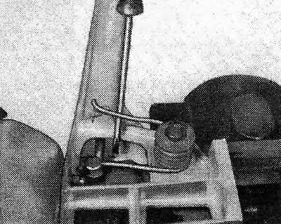
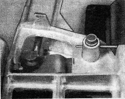
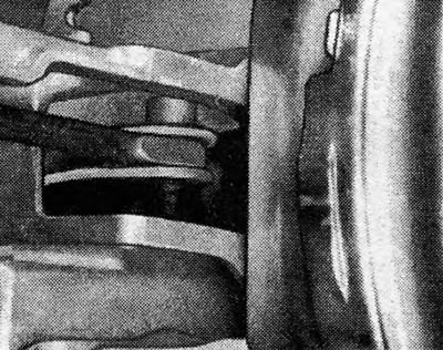
37. Assembly is carried out in reverse order. If you installed a new servo assembly, then adjust the servo push rod at the bracket to make 1.0 mm (0.04d) pedal clearance. Tighten the lock nut when adjustment is complete (photo).
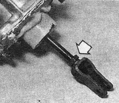
Photo 23.37 Servo bracket and lock nut (indicated by an arrow). Note the putty on the flange.
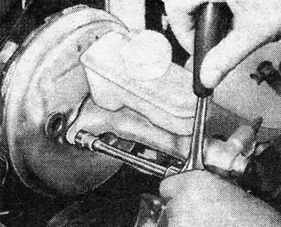
Pic. 9.44 — Unscrewing the main cylinder from the servo unit
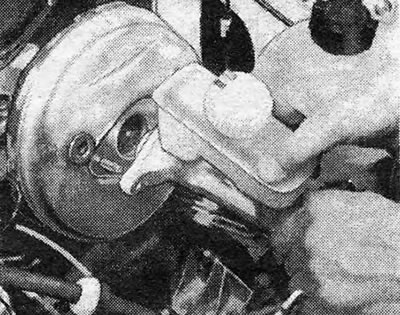
Pic. 9.45 — Removing the main cylinder from the servo unit
Pic. 9.52 — Pivot of the remote control rod at the servo unit
Pic. 9.56 — Disconnecting the crank arm from the push rod of the servo unit
Pic. 9.58 — Boot of the brake pedal pin case
Pic. 9.59 — Brake pedal installation diagram. The rubber stopper is indicated by the arrow
Visitor comments