


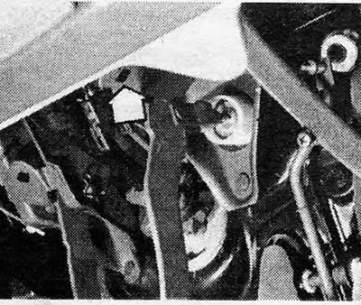
Photo 31.1 Keyhole switch support (indicated by the arrow)
2. To remove this switch, disconnect the electrical wires, rotate the switch 180 degrees so that the keys are aligned with the slots, and remove the switch.
3. Assemble in the reverse order, but before installation, pull out the switch plunger to its maximum distance.
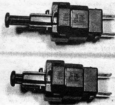
Photo 31.3 Switch with plunger fully extended (top) and with plunger retracted (bottom)
4. The plunger will automatically adjust itself during use, but check that it works if the brake pedal travel exceeds 15 - 25 mm (0.6 - 1.0 d).
Visitor comments