
Adjustment
Tuning lines 76/756 EWG or ECE-R48 include checking and adjusting the vehicle's headlights. Proper adjustment of the headlights of the car should provide the best illumination of the road with low beams with the least blinding of oncoming traffic. In this case, the inclination of the light beams of the headlights to a flat surface and their direction to the vertical longitudinal central plane of the vehicle must comply with the conditions provided for in the tuning line.
Blindness (dipped beam) is considered eliminated if the intensity of lighting at a distance of 25 m from each individual headlight on a plane vertical to the roadway and at the height of the headlights and above does not exceed 1 lux. This requirement is met if the headlights are adjusted in accordance with the adjustment instructions.
On the body of the front (basic) headlight or on the mount there is a dipped beam adjustment, according to the setting line 76/756 EWG or ECE-R48, indication: 1.0%.
The specification 1.0% corresponds to the installation dimension of the headlamp in relation to the inclination of the beam. So the slope at a distance of 10 m from the headlights of the car is 10 cm (L0017601 and L0017602). The low beam headlamp tilt indicator is considered to be the light-dark boundary.
Note. The adjustment instruction is explained by drawings.
The abbreviations used are:
- A - horizontal distance between the centers of the headlights;
- B - central mark;
- C - test surface;
- D - occupied area;
- E - transition point;
- e - installation size in cm;
- e = H - h = (installation dimension, headlights 1.0%, e = 10 cm, fog lights 2%, e = 20 cm).
- H - the height of the middle of the headlight above the occupied area;
- H is the height of the light-dark border of the dipped beam headlight above the surface on which the car is standing.
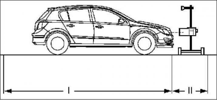
The headlights are adjusted using the adjuster according to the instructions as shown in the pictures.
The supporting surface of the measuring device and the vehicle must form a level surface. Surface roughness can be maximum±0.5mm/m.
I =±1.0 mm/m.
II =±0.5 mm/m.
The tires of the vehicle must have the air pressure specified in the instructions. Defective glass and headlight reflectors, as well as soot-covered incandescent lamps, must be replaced before adjustment.
Adjustment is carried out with the dead weight of the vehicle with one person or a load of 75 kg on the driver's seat. (Unladen weight of the vehicle = the mass of the vehicle ready for driving with a full fuel tank and the mass of all equipment parts involved in the operation of the vehicle, e.g. spare wheel, tools, jack, first aid kit, warning triangle, etc.).
On vehicles with manual ride height adjustment, the prescribed main pressure must be set (0.8 bar at unladen vehicle weight).
When manually adjusting the ride height, turn on the ignition and set the light switch unit adjuster to «0».
Intersection point of the horizontal and ascending parts of the light-dark boundary (transition point) must be on a perpendicular line that passes through the center mark.
In order to facilitate the calculation of said intersection point, it is possible to alternately close and reopen half of the headlight several times.
The headlight adjustment devices used must match the existing setting lines and the manufacturer's instruction manual must be followed.
A regular check of the headlight adjustment device must be initiated by the manufacturer's customer service.
The headlamp leveling device is adjusted according to the manufacturer's instructions and is set at 1.0% tilt for low beams or 2% tilt for front fog lamps.
According to directive 76/756 EWG, there is no 15°line for dipped beam on the measurement screen (the figure shows the installation for right-hand traffic). The direction of adjustment can also be made using the headlight adjustment instruments, which show a 15°line on the measurement screen.
The middle of the high beam beam must be located inside the restrictive corners at the center mark (drawing) for headlights with the possibility of setting low and high beams.
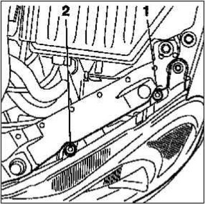
Headlights:
- 1 - height adjustment;
- 2 - direction adjustment.
The headlights must be installed on a headlight adjustment screen that complies with the instructions or with a headlight adjustment tool.
Height adjustment
The light-dark boundary on the left must run from the adjustment crosshairs horizontally along the adjustment line.
Direction adjustment
The light-dark boundary must run horizontally from the left side to the adjustment crosshairs and from there at an angle of approximately 15°to the right upwards. The slope of the light beam is 1.0% at 10 m.
First you need to adjust the height, then adjust the direction. After adjusting the direction, check the height adjustment again.
Visitor comments