


Attention! Do not neglect the work on adjusting the headlights. In addition to the fact that your car with unadjusted headlights will not pass the instrumental check at the next technical inspection, it will be dangerous on the road for all road users, including you. The actions of a driver blinded by the headlights of an oncoming car are often unpredictable.
You will need: allen key "6", Phillips-head screwdriver.
1. Pre-check and, if necessary, adjust the air pressure in the tires to the correct level.
2. Position the car perpendicular to a smooth wall (for example, in the garage) at a distance of 10 m. Place an additional 75 kg load on the driver's seat.
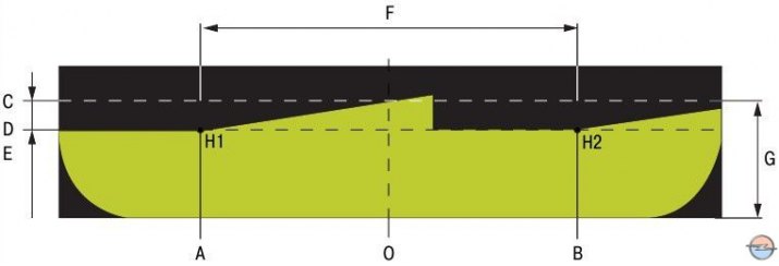
Fig. 1. Headlight adjustment: A, B - vertical lines indicating the location of the centers of the low beam lamps of the left and right headlights; C — horizontal line corresponding to the centers of the headlights; D — line passing through the centers of light spots; E — distance between lines C and D (E = 130 mm); F — distance between the centers of the low beam headlights; G — the distance from the centers of the headlights to the surface on which the car is located
Mark the screen on the wall as shown in Fig. 1. The longitudinal plane of symmetry of the car should pass along the line 0 on the screen. Rock the car from the side to allow the suspension springs to self-align.
3. Measure the height of the headlight centers from the floor on your vehicle. This will be the distance G on the screen.
4. Set the headlight beam adjuster on the instrument panel to the position corresponding to the load of the vehicle with one driver.
5. Turn on the low beam.
6. It is recommended to adjust the direction of the light spot for each headlight separately. Cover the second headlight with opaque material during adjustment.
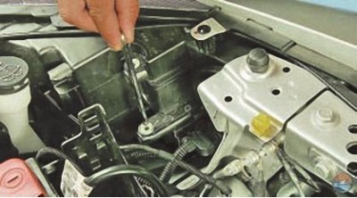
7. Open the hood and, by turning the adjusting screws, adjust the position of the light spot on the screen for each headlight horizontally..
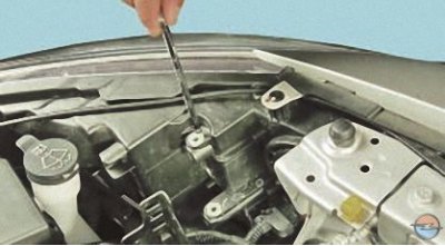
8. …and vertically, if the location of the light spots does not correspond to the drawing.
9. The headlights are considered adjusted when the upper borders of the left parts of the light spots coincide with the line 4, and vertical lines 1 and 2 pass through the points E1 and E2 intersections of horizontal and inclined sections of light spots.
The direction of the fog light beam can only be adjusted in height.
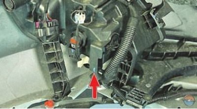
From underneath the car, through the gap between the lower edge of the front bumper and the body, turn the adjusting screw with a long Phillips-head screwdriver, ensuring that the upper edges of the light spots are on the line WITH (Fig. 2) or slightly below it.
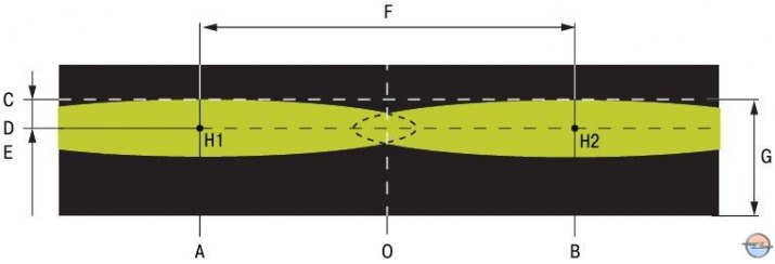
Fig. 2. Adjusting the fog lights: A, B – vertical lines indicating the location of the centers of the low beam lamps of the left and right headlights; C – horizontal line corresponding to the centers of the headlights; D – line indicating the height of the horizontal boundary of the light beams; E – distance between lines C and D (E = 199 mm); F – distance between the centers of the low beam headlights; G – distance from the centers of the headlights to the surface on which the car is located
Note: Shown with bumper removed for clarity.
Visitor comments