
2. Having removed the servo assembly and remote control assembly as indicated in the previous Section, remove the snap ring that secures the crank pin in the case to the remote control rod on the brake pedal side (photo).
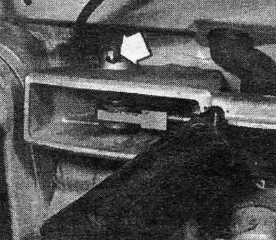
Photo 24.2 Crank pin ring (models before 1985)
3. Remove the kingpin (Pic. 9.60).
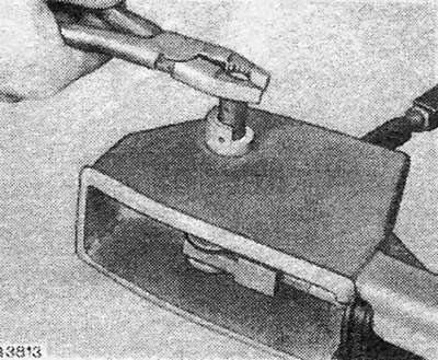
Pic. 9.60 — Removing the crank pin
4. Remove the remote control rod and crank from the case.
5. The bellcrank can be separated from the remote control rod after removing the snap ring.
6. The crank arm must be replaced along with the pedal push rod.
7. Assembly is carried out in reverse order; lubricate the pins and adjust the remote control rod as indicated in Section 23, paragraphs 23 and 24.
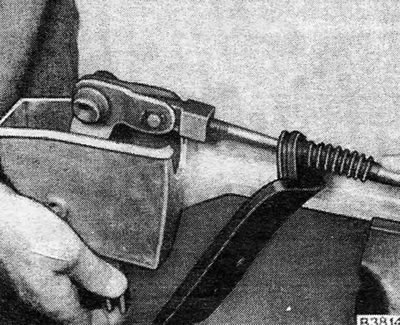
Pic. 9.61 - Removing the remote control crank from the case at the end of the rod on the pedal side
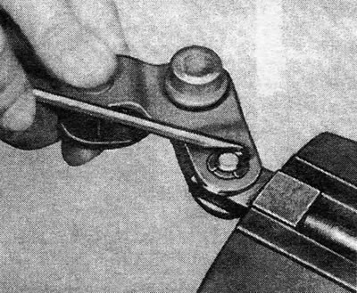
Pic. 9.62 - Removing the snap ring to separate the crank and remote control rod
Visitor comments