
OpelBook.ru
Cars AvtoVAZ Cars Mitsubishi Cars BMW Cars Mercedes Cars Nissan Cars Toyota Cars Chevrolet
English Русский
Български
Беларускі
Український
Српски
Hrvatski
Română
Polski
Slovenský
Magyar
 |  Sitemap  |  Contacts  |    


Main Astra Corsa Insignia Kadett Omega Vectra Zafira Others Articles
Frontera A (1991-1998, petrol) Frontera B (1998-2004) Ascona C (1981-1988) Vivaro A (2001-2014)
  • Main
  • Opel
  • Ascona C
  • Chassis
  • Brake system
  • Self-adjusting rear brakes — inspection and replacement

Self-adjusting rear brakes — inspection and replacement (Opel Ascona C)

            0

Inspection.


1. Proceed as described in paragraphs 1 and 2 Section 9.

2. Lock the front wheels and engage gear. Loosen the rear wheel nuts on the working side, then jack up the rear of the car and remove the wheel. Release the handbrake.

3. Remove the brake drum mounting screw and remove the drum. If it is tight, release the brake shoes by removing the plug in the rear brake plate and pushing the handbrake control lever outward with a screwdriver (Figure 9.27).
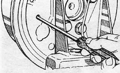
Figure 9.27. Release the handbrake lever by inserting a screwdriver through the hole

Figure 9.27. Release the handbrake lever by inserting a screwdriver through the hole


4. Remove the studs and rings or springs and gaskets. Replace them if they are damaged (photo).

Article posted on an online resource: OpelBook.ru
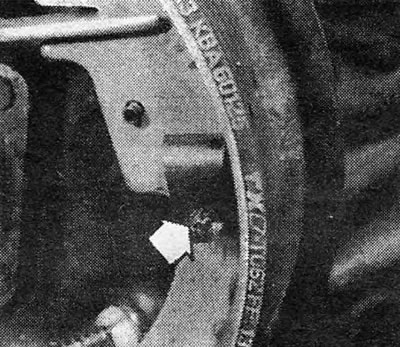
Photo 11.4A Brake shoe ring (universal). Turn the retaining device (indicated by the arrow) 90…

Photo 11.4A Brake shoe ring (universal). Turn the retaining device (indicated by the arrow) 90 degrees...
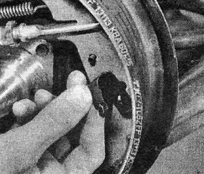


Photo 11.4B....and remove the ring.

Photo 11.4B....and remove the ring.


5. Disconnect the handbrake cable from the control lever (photo). If there is not enough slack in the cable, disconnect it near the equalizer.
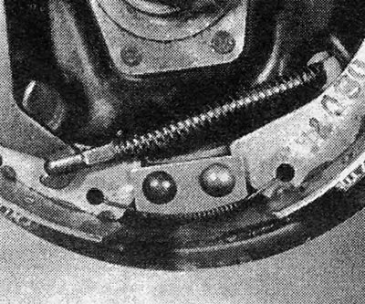
Photo 11.5 Disconnect the handbrake cable.

Photo 11.5 Disconnect the handbrake cable.


6. Now you can unhook the return springs and remove the shoes individually, or the shoe assembly, spacer and springs can be removed as a whole. The second way is especially easy if the rear hub is removed, as was done for the purpose of taking the photographs. Be careful not to damage the rubber cylinder wraps.

7. Clean the rear brake disc without inhaling the powder or spraying it into the air. (Original liners are now manufactured asbestos free, but this may not apply to other liners.)


8. Identify and eliminate the source of lining contamination before installing new shoes.

9. Disassemble the shoes, spacer and springs. Pay attention to how the springs are installed and how the strut is positioned. Don't confuse left- and right-hand parts: On all models except station wagons, the threaded rod is marked "L" or "R", and other components of this kind are color-coded "black" for the left side and color-coded "silver" for the right side (photo).
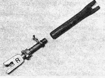
Photo 11.9 Self-adjusting rack components - right side.

Photo 11.9 Self-adjusting rack components - right side.


10. Disassemble and clean the adjusting spacer. Lubricate the threads with silicone based lubricant.

11. If a new handbrake shoe lever was not supplied with the new shoes, use the old one. It may be secured with a pin and snap ring (photo), or with a rivet that will need to be drilled out.
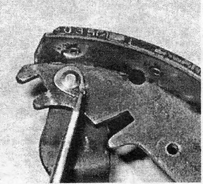
Photo 11.11 Handbrake lever secured with a pin and spring ring.

Photo 11.11 Handbrake lever secured with a pin and spring ring.


12. Assemble the new shoes, springs and adjusting components. Place the return springs into their holes in the new shoes and position the self-adjusting components. The threaded spacer must be clean and lightly greased and fully retracted, which is done using a sprocket wheel before installing it between the shoes. Please note that the shorter leg of the strut fork should be facing you. On models with a closed body ("saloon") and with an upward-opening rear door ("hatchback"), it is necessary to replace the spring that secures the kingpin of the adjusting lever to the shoe webbing. Please refer to the corresponding accompanying photos for assembly details.
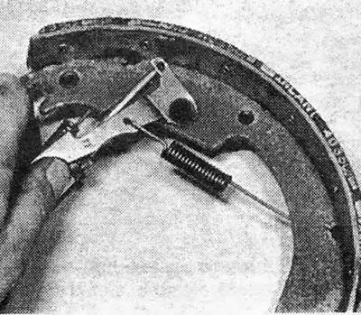
Photo 11.12A Installing the control lever («station wagon»).

Photo 11.12A Installing the control lever ("station wagon").
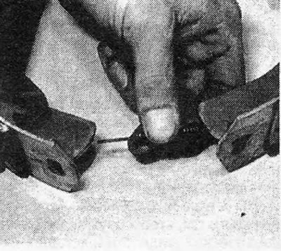

Photo 11.12B Installing the lower return spring («universal»).

Photo 11.12B Installing the lower return spring ("universal").
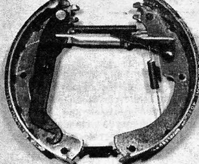


Photo 11.12C Rear brake components prepared for installation («wagon»).

Photo 11.12C Rear brake components prepared for installation ("wagon").
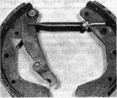

Photo 11.12D Correctly installed self-adjusting strut («salon» / «hatchback»).

Photo 11.12D Correctly installed self-adjusting strut ("salon" / "hatchback").
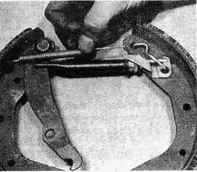

Photo 11.12E Installing the upper return spring («salon» / «hatchback»).

Photo 11.12E Installing the upper return spring ("salon" / "hatchback").
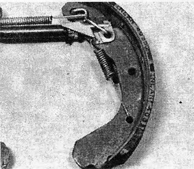

Photo 11.12F Adjustment arm spring installed (saloon/hatchback).

Photo 11.12F Adjustment arm spring installed (saloon/hatchback).


13. Before installing the brake shoe assemblies into place, lubricate the friction areas of the shoes on the rear brake plate with a copper-based anti-seize compound.

14. Place the shoes on the rear brake plate. Be careful not to damage the cylinder wrappings or displace the pistons. Once the shoes are in place, insert and secure the studs. Reconnect the handbrake cable and install and adjust the hub if it was removed (photo).
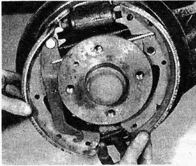
Photo 11.14A Installing rear brake components (station wagon).
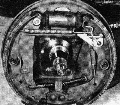
Photo 11.14A Installing rear brake components (station wagon).


Photo 11.14B Rear brake components installed - hub removed for clarity («interior» / «hatchback»).

Photo 11.14B Rear brake components installed - hub removed for clarity ("interior" / "hatchback").


15. If you find it very difficult to install the shoes and springs together, it is possible to install the shoes and secure them with studs, then leave the adjusting spacer and install the springs and adjusting lever.


16. Feed the adjusting gear back to reduce the length of the spacer until the brake drum is positioned over the new linings. make sure the handbrake lever is positioned correctly (the pin is on the edge of the shoe webbing, not on top of it). Install and secure the brake drum.

17. Repeat these steps with the other rear brake, then adjust the brakes by applying the foot brake (saloon and hatchback models) or hand brake (station wagon model) at least ten times. You will hear a clicking sound indicating that the automatic regulators are working; when it stops, the adjustment will be complete.

18. Check the handbrake adjustment and adjust it if necessary (Section 26).

19. After installing new linings, avoid hard braking for several hundred miles to allow the linings to bed in.


This article is available at russian, bulgarian, belarusian, ukrainian, serbian, croatian, romanian, polish, slovak, hungarian
Checking the article: Kornev Georgy

Share information:

Previous articles
Opel Ascona C: Brake system
Next articles

Self-adjusting rear brakes — description
Rear Brake Shoes (Pre-1984 Models) — Inspect and Replace
Rear brakes (on models manufactured before 1984) — lining
Brake Disc Shield — Removal and Installation
Brake disc — inspection, removal and installation
Caliper (type GMF) — removal, inspection and installation
Rear Brake Cylinder — Removal, Inspection and Installation
Rear Brake Plate — Removal and Installation
Brake Drum — Inspection and Renewal
Master Brake Cylinder — Removal and Installation
Master Cylinder (ATE Type) — Inspection and Repair
Master Cylinder (GNF Type) — Inspection


See similar ones from other Opel car manuals:
▶ Adjusting the rear view mirrors Opel Astra G (1998-2004, petrol)
▶ Rear brakes Opel Corsa C (2000-2006, petrol)
▶ Technical characteristics of rear wheel drum brakes Opel Kadett E (1984-1995)
▶ Adjusting the rear view mirrors Opel Vectra A (1988-1995, petrol)
▶ Adjusting the rear view mirrors Opel Zafira A (1999-2005, petrol)
Link to this page in different formats

Visitor comments


No comments yet


How much will 36 + 17 =


Vivaro A (2001-2014) 
  • General information
  • User manual
  • Power unit
  • Petrol engine F4R
  • Diesel engine F9Q
  • Diesel engine G9U
  • Transmission
  • Clutch and drive shafts
  • Manual gearbox
  • Chassis
  • Front suspension
  • Rear suspension
  • Brake system
  • Body
  • Exterior
  • Interior
  • Electrical equipment
  • Heating and ventilation
  • Air conditioner
  • Equipment and devices
  • Electrical diagrams
Ascona C (1981-1988) 
  • General information
  • Maintenance
  • Power unit
  • Gasoline engines
  • Diesel engines
  • Cooling system
  • Fuel and exhaust system
  • Contact ignition system
  • Contactless ignition system
  • Transmission
  • Clutch
  • Mechanical gearbox
  • Automatic gearbox
  • Drive shafts
  • Chassis
  • Steering
  • Brake system
  • Car suspension
  • Body
  • Exterior
  • Interior
  • Doors and windows
  • Electrical equipment
  • Equipment and devices
  • Power devices
  • Electrical circuits
Frontera B (1998-2004) 
  • General information
  • User manual
  • Maintenance
  • Power unit
  • Petrol engines 2.2 l
  • Petrol engines 3.2 l
  • Diesel engines 2.2 l
  • Cooling system
  • Fuel system (petrol)
  • Fuel system (diesel)
  • Ignition system
  • Transmission
  • Clutch
  • Manual gearbox MUA5C
  • Automatic gearbox 4L30E
  • Chassis
  • Suspension and axles
  • Steering
  • Brake system
  • Body
  • Exterior
  • Interior
  • Doors, locks and windows
  • Heating and air conditioning
  • Electrical equipment
  • Power devices
  • Equipment and devices
  • Lighting and signaling
  • Electrical diagrams
Frontera A (1991-1998, petrol) 
  • General information
  • Introduction to guide
  • User manual
  • Maintenance
  • Power unit
  • Engine repair
  • Lubrication system
  • Cooling system
  • Power and exhaust system
  • Engine electrics
  • Transmission
  • Clutch
  • Mechanical gearbox
  • Cardan shafts
  • Chassis
  • Brake system
  • Front suspension
  • Rear suspension
  • Steering
  • Body
  • Repair and care
  • Electrical equipment
  • Equipment and devices
  • Electrical circuits
OpelBook.ru © 2017–2026 · Mobile version · · Sitemap: EN BG BY UA RS HR RO PL SK HU · Feedback · Site search
Astra F, petrol · Astra G, petrol · Astra G · Astra H · Astra J, petrol · Corsa B · Corsa C, petrol · Corsa C · Insignia A · Kadett D · Kadett E · Omega A · Omega B · Omega B2 · Vectra A, petrol · Vectra A · Vectra B, petrol · Vectra B · Vectra C · Zafira A, petrol · Frontera A, petrol · Frontera B · Ascona C · Vivaro A ·
We want your visit to be comfortable 🤝! We use cookies 🍪 to make that happen.