
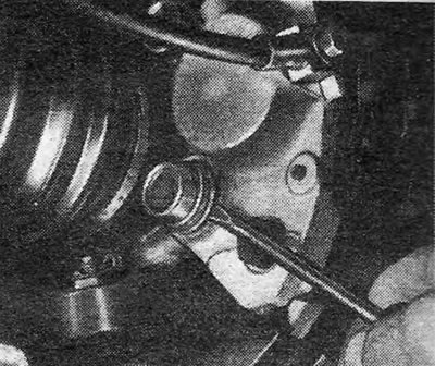
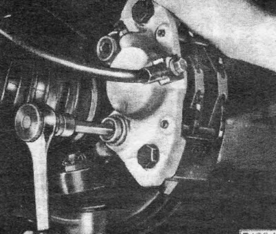
2. Remove the caps of the mounting bolts (photo). Do not remove the two octagon head bolts as they connect the caliper body and the bracket.
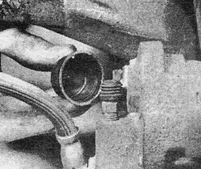
Photo 5.2 Remove the caliper bolt cap (type GMF).
3. Disconnect the fluid tube from the caliper and either seal it with rubber rings or allow the fluid to drain into a container.
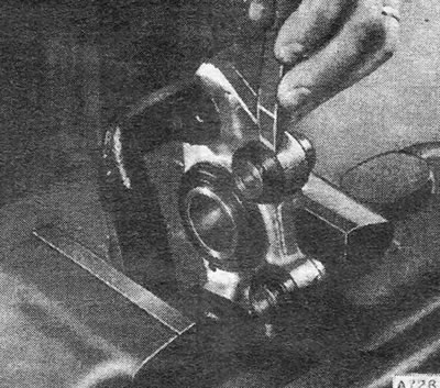
4. Using an Allen wrench, unscrew the two socket-head mounting bolts (photo).
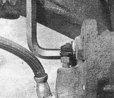
Photo 5.4 Unscrew the caliper bolt (type GMF).
5. Remove the caliper from the machine.
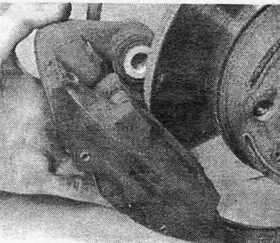
Photo 5.5 Removing the caliper
6. Brush off any external dirt and remove the disc pads as indicated in Section 3.
7. Using a chisel, free the sliding inner caps from dust from the caliper case (Pic. 9.13).
8. Remove the piston boot (Pic. 9.14).
9. Apply pressure to the outer ends of the sliding cuffs until it is possible to separate their caps from the dust from the cuff grooves and remove them.
10. Remove the sliding collars from the caliper case (Pic. 9.15).
11. Follow the steps described in Section 4, paragraphs 9-15.
Pic. 9.11 — Removing the caps of the caliper mounting bolts (GMF)
12. Install the new boot into the groove on the piston when the piston is already partially inserted.
Pic. 9.12 — Removing the mounting bolt with a socket head (GMF)
13. Replace the seal rings on the sliding seals, using the special lubricant provided in the repair kit on the grooves of the seal rings. Make sure the seal ring is located in the center groove.
Pic. 9.13 — Removing the internal dust caps from the sliding cuffs (GMF)
14. Install the sliding collars so that the groove of the dust cap faces the caliper bracket. Do not push the cuffs all the way in at this stage. Install new dust caps for the sliding seals in their place on the caliper. For their final installation, use a piece of pipe.
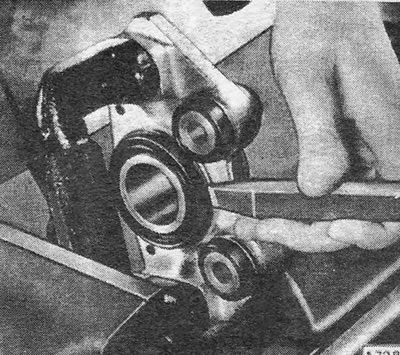
Pic. 9.14 — Removing the piston boot (GMF)
15. Press the piston in completely and secure the boot to the case, placing it in place using a piece of suitable pipe.
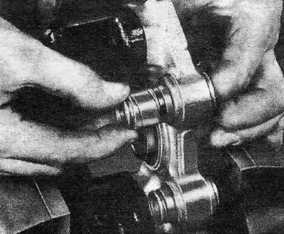
Pic. 9.15 — Removing the sliding caliper cuffs (GMF)
16. Reinstall the caliper, screw in and tighten the flare head mounting bolts, after cleaning the threads and lubricating them with a thread locking compound.
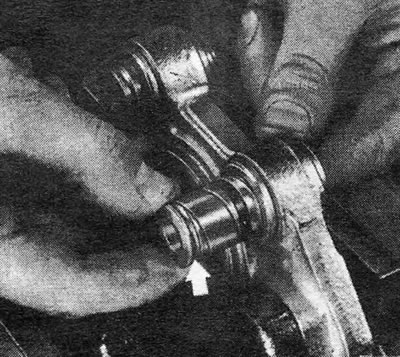
Pic. 9.16 — The correct location of the groove of the dust cap of the sliding cuff is indicated by the arrow. (GMF)
17. Install the bolt caps.
18. Reconnect the fluid hose using new seals.
19. Install the disc pads as indicated in Section 3.
20. Bleed the hydraulic system as indicated in Section 20.
21. Install the wheels and lower the machine.
Visitor comments