
OpelBook.ru
Cars AvtoVAZ Cars Mitsubishi Cars BMW Cars Mercedes Cars Nissan Cars Toyota Cars Chevrolet
English Русский
Български
Беларускі
Український
Српски
Hrvatski
Română
Polski
Slovenský
Magyar
 |  Sitemap  |  Contacts  |    


Main Astra Corsa Insignia Kadett Omega Vectra Zafira Others Articles
Frontera A (1991-1998, petrol) Frontera B (1998-2004) Ascona C (1981-1988) Vivaro A (2001-2014)
  • Main
  • Opel
  • Ascona C
  • Chassis
  • Brake system
  • Caliper (type ATE) — removal, inspection and installation

Caliper (type ATE) — removal, inspection and installation (Opel Ascona C)

            0

1. Raise the front of the car and remove the brake pads (Section 3).

2. Loosen and remove the caliper fluid coupling bolt. Plug the coupling with two suitable rings or allow the liquid to drain into a container.

3. On older models, remove the two caliper mounting bolts and remove the caliper.

4. On later models, remove the caliper from the mounting plate by pushing the caliper inward from the front (towards the wheel hub) and at the same time moving the caliper towards the center of the car.

5. Clean off any external dirt from the caliper assembly without inhaling the powder. Clamp the caliper in a vice. Use a soft jaw on the vice and be careful not to damage or bend the caliper.

6. On older models, separate the caliper body from its bracket by lifting it off its keyways (Figure 9.4).
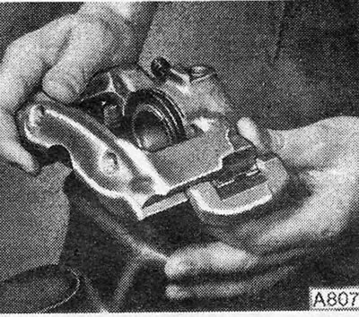
Figure 9.4 - Disconnecting the ATE type caliper body from the bracket (old type)

Figure 9.4 - Disconnecting the ATE type caliper body from the bracket (old type)


7. Using a screwdriver, remove the retaining ring from the boot (Figure 9.5).
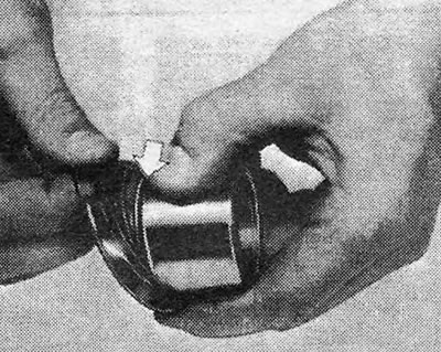
Figure 9.5 - Removing the boot retaining ring

Figure 9.5 - Removing the boot retaining ring


8. Remove the dust cover (Figure 9.6).
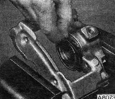
Figure 9.6 - Removing the caliper boot

Figure 9.6 - Removing the caliper boot


9. Place a thin piece of wood or cardboard on the end of the piston and apply compressed air to the tube connection on the caliper body. To remove the piston, you will need a little air pressure, such as from a foot tire pump.

10. After removing the piston, pull the oil seal out of its groove in the cylinder using a plastic or wooden tool.

11. Inspect the piston and cylinder bore surfaces for scratches or signs of metal-to-metal friction. If the damage is not in doubt, replace the caliper completely.

12. If these components are in good condition, then discard the rubber seal and boot and purchase a repair kit that contains all the necessary spare parts.

13. The rubber guides of the latest type of caliper can be replaced if necessary. Remove the nylon compression sleeve from each rubber guide, then gently squeeze the collar of the sleeve and press it down to remove it from the inside (photo).
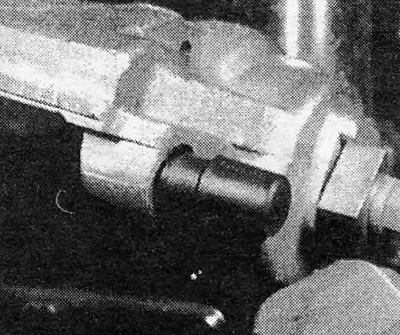
Photo 4.13A Remove the nylon compression cuff...
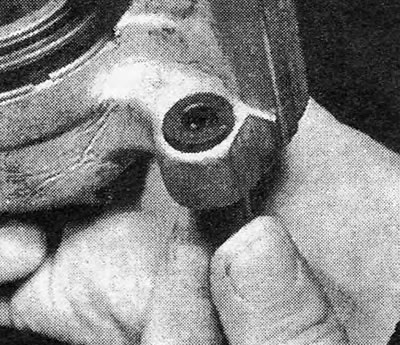
Photo 4.13A Remove the nylon compression cuff...


Photo 4.13B... and remove the rubber bushing from the caliper (last type).

Photo 4.13B... and remove the rubber bushing from the caliper (last type).


14. Clean the piston and cylinder bore with hydraulic fluid or methylated spirits - nothing else.

(The article was published on the website: «www.OpelBook.ru»)

15. Begin assembly by installing the seal into the groove of the cylinder (Figure 9.7).
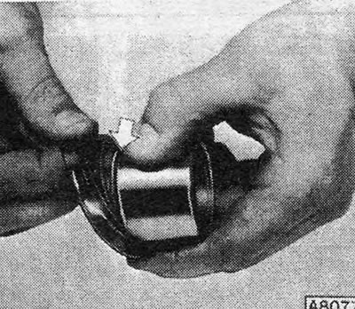
Figure 9.7 — Engagement of the dust cover in the piston groove

Figure 9.7 — Engagement of the dust cover in the piston groove


16. Position the dust boot in its groove in the piston. Dip the piston in clean brake fluid or lubricate its outer surface with rubber grease and insert it into the cylinder at a right angle. Make sure the piston is positioned as shown in Figure 9.8.
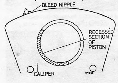
Figure 9.8 - Caliper piston installation diagram

Figure 9.8 - Caliper piston installation diagram


17. When the piston is partially depressed, connect the dust boot to the cylinder rim and install the retaining ring.

18. Press the piston so that it goes completely into the cylinder barrel.

19. If you are dealing with the latest type of caliper, install the rubber guide bushing and insert the compression seal. Do not damage the guide bushing and collar during installation and make sure that the flange of the rubber guide bushing is fully engaged (photo).
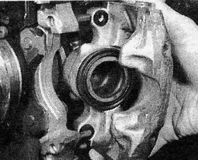
Photo 4.19 Guide bushing reinstalled on caliper (last type).

Photo 4.19 Guide bushing reinstalled on caliper (last type).


20. On older models, secure the caliper bracket in a vice and install the spring guides (Figure 9.9). Install the caliper body into the caliper keyways so that the body and caliper are positioned close to each other (Figure 9.10).
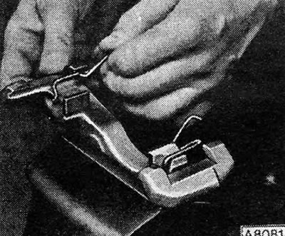
Figure 9.9 — Installing the caliper bracket spring guides
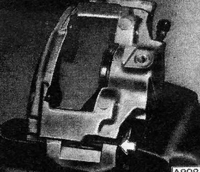
Figure 9.9 — Installing the caliper bracket spring guides


Figure 9.10 - Caliper body and bracket connected at the same level - location indicated by arrow

Figure 9.10 - Caliper body and bracket connected at the same level - location indicated by arrow


21. Install the caliper onto the hub carrier. On older models, clean the threads of the mounting bolts and lubricate them with a thread-locking compound. Install the bolts, tighten them to the specified torque value, and then install the disc pads as shown in Section 3. On later models, install the caliper onto the guide pins and push it into place (photo), then install the disc pads.
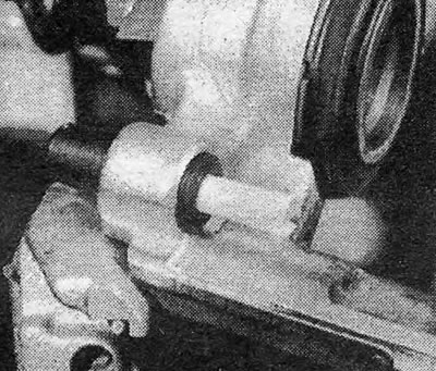
Photo 4.21 New type caliper assembly (ATE type).

Photo 4.21 New type caliper assembly (ATE type).


22. Connect the fluid hose using new seals in the coupling.

23. Blow the system as indicated in Section 20.

24. Install the wheel, paying attention to the alignment marks, and lower the car to the ground. Press the brake pedal several times to bring the pads to the disc, then add fluid to the master cylinder if necessary.


This article is available at russian, bulgarian, belarusian, ukrainian, serbian, croatian, romanian, polish, slovak, hungarian
Checking the article: Kornev Georgy

Share information:

Previous articles
Opel Ascona C: Brake system
Next articles

Disc pads — inspection and replacement
Routine maintenance
General description
Brake system — specifications
Caliper (type GMF) — removal, inspection and installation
Brake disc — inspection, removal and installation
Brake Disc Shield — Removal and Installation
Rear brakes (on models manufactured before 1984) — lining
Rear Brake Shoes (Pre-1984 Models) — Inspect and Replace
Self-adjusting rear brakes — description


See similar ones from other Opel car manuals:
▶ Front Brake Caliper — Removal, Repair and Installation Opel Astra F (1991-1998, petrol)
▶ Features of replacing a tripod type CV joint (Z10XE engines) Opel Corsa C (2000-2006)
▶ Dial type indicator Opel Insignia A (2008-2017)
▶ The device of the 4-speed gearbox type «F16» Opel Kadett E (1984-1995)
▶ Front Brake Caliper — Removal, Repair and Installation Opel Omega A (1986-1993)
Link to this page in different formats

Visitor comments


No comments yet


How much will 39 + 15 =


Vivaro A (2001-2014) 
  • General information
  • User manual
  • Power unit
  • Petrol engine F4R
  • Diesel engine F9Q
  • Diesel engine G9U
  • Transmission
  • Clutch and drive shafts
  • Manual gearbox
  • Chassis
  • Front suspension
  • Rear suspension
  • Brake system
  • Body
  • Exterior
  • Interior
  • Electrical equipment
  • Heating and ventilation
  • Air conditioner
  • Equipment and devices
  • Electrical diagrams
Ascona C (1981-1988) 
  • General information
  • Maintenance
  • Power unit
  • Gasoline engines
  • Diesel engines
  • Cooling system
  • Fuel and exhaust system
  • Contact ignition system
  • Contactless ignition system
  • Transmission
  • Clutch
  • Mechanical gearbox
  • Automatic gearbox
  • Drive shafts
  • Chassis
  • Steering
  • Brake system
  • Car suspension
  • Body
  • Exterior
  • Interior
  • Doors and windows
  • Electrical equipment
  • Equipment and devices
  • Power devices
  • Electrical circuits
Frontera B (1998-2004) 
  • General information
  • User manual
  • Maintenance
  • Power unit
  • Petrol engines 2.2 l
  • Petrol engines 3.2 l
  • Diesel engines 2.2 l
  • Cooling system
  • Fuel system (petrol)
  • Fuel system (diesel)
  • Ignition system
  • Transmission
  • Clutch
  • Manual gearbox MUA5C
  • Automatic gearbox 4L30E
  • Chassis
  • Suspension and axles
  • Steering
  • Brake system
  • Body
  • Exterior
  • Interior
  • Doors, locks and windows
  • Heating and air conditioning
  • Electrical equipment
  • Power devices
  • Equipment and devices
  • Lighting and signaling
  • Electrical diagrams
Frontera A (1991-1998, petrol) 
  • General information
  • Introduction to guide
  • User manual
  • Maintenance
  • Power unit
  • Engine repair
  • Lubrication system
  • Cooling system
  • Power and exhaust system
  • Engine electrics
  • Transmission
  • Clutch
  • Mechanical gearbox
  • Cardan shafts
  • Chassis
  • Brake system
  • Front suspension
  • Rear suspension
  • Steering
  • Body
  • Repair and care
  • Electrical equipment
  • Equipment and devices
  • Electrical circuits
OpelBook.ru © 2017–2026 · Mobile version · · Sitemap: EN BG BY UA RS HR RO PL SK HU · Feedback · Site search
Astra F, petrol · Astra G, petrol · Astra G · Astra H · Astra J, petrol · Corsa B · Corsa C, petrol · Corsa C · Insignia A · Kadett D · Kadett E · Omega A · Omega B · Omega B2 · Vectra A, petrol · Vectra A · Vectra B, petrol · Vectra B · Vectra C · Zafira A, petrol · Frontera A, petrol · Frontera B · Ascona C · Vivaro A ·
We want your visit to be comfortable 🤝! We use cookies 🍪 to make that happen.