


Contents: Removal ⬇ Disassembly ⬇ Examination ⬇ Replacing the valve guide bushing ⬇ Replacing the valve seat ⬇ Valve grinding ⬇ Assembly ⬇ Installation ⬇
Warning! To avoid damaging the cylinder head due to temperature changes, remove the cylinder head on a cold engine.
Removal
Disconnect the cable from the negative battery terminal.
To access the cylinder head mounting bolts, remove the cylinder head cover.
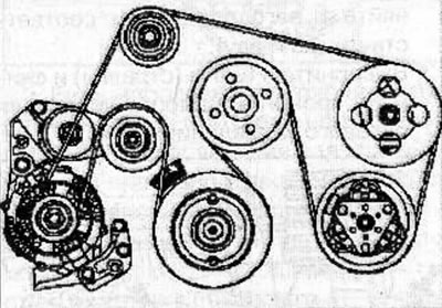
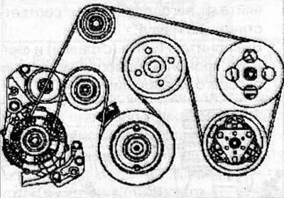
Remove the accessory drive belt (see the relevant chapter).
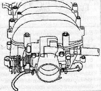
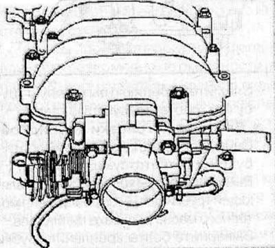
Remove the expansion chamber (see the relevant chapter).
Remove the radiator (see the relevant chapter).
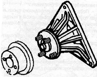
Unscrew 4 nuts and remove the radiator fan from the viscous coupling pulley.
Remove 2 bolts and 2 nuts and remove the fan pulley assembly from the cylinder block.
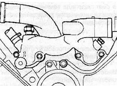
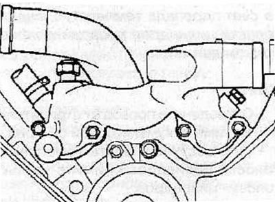
Remove 4 bolts, disconnect coolant hoses and connectors and remove coolant manifold from cylinder head.
For left cylinder head:
Remove the power steering pump without disconnecting the hoses from it (see the relevant chapter).
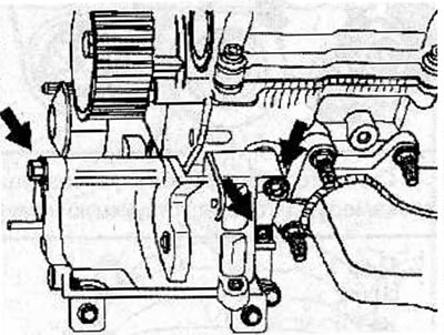
Remove 3 bolts (arrows) and power steering pump bracket.
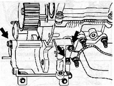
Remove the front exhaust pipe (see the relevant chapter).
For right cylinder head:
Remove the front exhaust pipe (see the relevant chapter).
Remove the bolts securing the guide tube for the engine oil level indicator to the cylinder head.
Remove the bolts securing the exhaust gas recirculation system tube to the cylinder head.
Remove the timing belt of the gas distribution mechanism drive (see the relevant chapter).
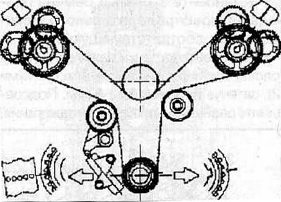
In the reverse order of tightening, use the MKM-134-A wrench to loosen the cylinder head mounting bolts in 2-3 passes.
Warnings:
- Failure to loosen the bolts in the correct sequence may result in deformation or cracking of the cylinder head.
- Loosen and unscrew the cylinder head mounting bolts in 2-3 passes.
Carefully remove the head from the cylinder block guide pins and place it on blocks on the work bench, being careful not to damage the mating surfaces of the head and cylinder block.
Disassembly
Remove the exhaust manifold (see the relevant chapter).
Remove the spark plugs using a spark plug wrench. To avoid damaging the spark plug, install the spark plug wrench strictly along the spark plug axis.
Remove the camshafts (see the relevant chapter).
Remove the valve lifters and adjusting washers from the cylinder head.
Label the valves. Using a special tool, compress the valve spring and remove the crackers from the valve stem. Remove the valve spring retainer and valve spring.
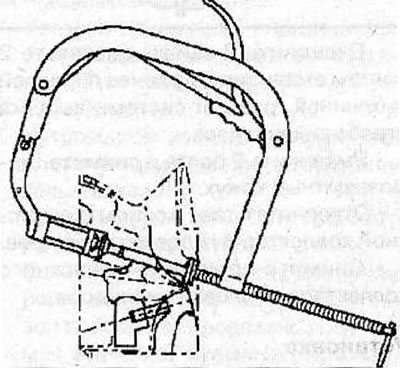
Using a special tool, remove the oil deflector cap from the valve guide sleeve.
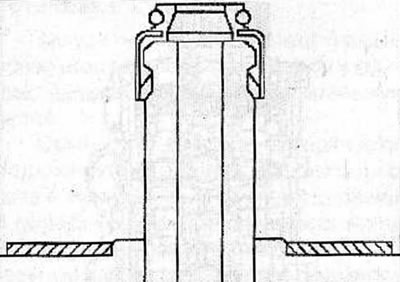
Remove the remaining valves from the cylinder head in the same manner.
Check the mating surfaces of the cylinder head and the working surfaces of the valve guide bushings and plain bearings for wear.
Examination
Checking the cylinder head
Clean the mating surfaces of the cylinder head.
Inspect the cylinder head for damage, cracks, oil and coolant leaks. Replace the cylinder head if necessary.
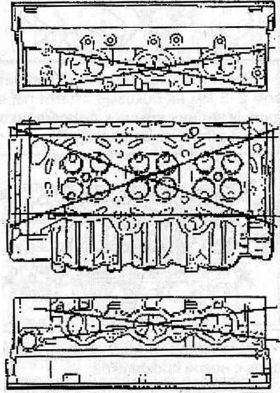
Using a metal ruler and feeler gauge, check the flatness of the cylinder head mating surface in several directions.
Checking the clearance between the valve guide and the valve stem
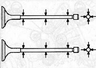
Using a bore gauge, measure the inside diameter of the valve guide bushings in several places.
Using a micrometer, measure the diameter of the valve stem in several places along the height.
Calculate the clearance between the valve guide and the valve stem. To do this, subtract the outside diameter of the valve stem from the inside diameter of the corresponding valve guide.
Example:
- Valve guide inner diameter: 5.999 mm
- Valve stem outside diameter: 5.969 mm
- Clearance between valve guide and valve stem: 0.030 mm
Maximum permissible clearance between the guide bushing and the valve stem:
- inlet valves: 0.20 mm
- exhaust valves: 0.20 mm
Replacing the valve guide bushing
Using the KM-J-37985 puller, knock out the valve guide bushing from the combustion chamber side.
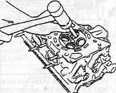
Lubricate the outside surface of the new valve guide with engine oil.
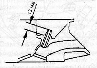
Using the KM-J-37985 puller and the KM-J-39204 adapter, press the new valve guide into the cylinder head from the camshaft side so that it protrudes 13 mm from the bearing surface of the cylinder head.
Measure the inner diameter of the valve guide bushing and if it is less than the permissible value, use a reamer to increase it to 6 mm.
Replacing the valve seat
Place the cylinder head on its end.
Arc weld a metal rod to the inside surface of the valve seat, being careful not to damage the cylinder head.
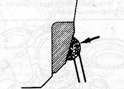
Wait a few minutes for the valve seat to cool down, during which time the valve seat will decrease in diameter due to the coefficient of thermal expansion.
Use the welded metal rod to remove the valve seat from the cylinder head.
Clean the valve seat thoroughly.
Heat the cylinder head, which will cause the valve seat to increase in size due to the coefficient of thermal expansion.
Cool the new valve seat with dry ice, this will cause the valve seat to shrink in size due to the coefficient of thermal expansion.
Using a press, press the new valve seat into the cylinder head socket, ensuring a press fit with an interference fit of 0.09-0.14 mm.
After pressing, process the working edges of the new valve seat, while precisely maintaining the working angle of the valve seat and the width of the working chamfer. Ensure that the valve seat insert surface contacts the entire working surface of the valve disc.
Lap the valve to the valve seat.
Valve grinding
If the valves are in satisfactory condition, they should be ground to the seats to ensure a tight seal that prevents gas leakage. If the seats have only minor damage or the seat has been reground, lapping can be done using a fine abrasive paste. Coarse lapping paste should only be used if traces of deep wear or severe burnout of the seats are detected. In this case, the cylinder head and valves should be checked by an experienced technician to determine whether the seats need to be machined or replaced.
The valve grinding is performed as follows. Place the cylinder head on a flat surface with the combustion chambers facing upward.
Apply lapping paste to the valve plate and valve seat, install the valve in place and install the suction cup with handle on the valve plate. Rotate the valve with a suction cup in different directions to grind the valve, and periodically lift the valve to redistribute the grinding paste. Lapping is made much easier if a not very stiff spring is placed under the valve head.
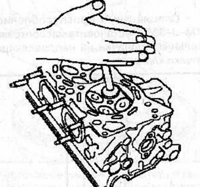
If a coarse lapping compound is used, lapping should be carried out until a uniform matte surface appears on the valve seat and valve. Then wipe off the used paste composition and repeat the lapping process with a fine paste. Continue grinding until a light grey-matte colour appears. Further grinding is not allowed, since excessive wear of the seat may make subsequent repair impossible.
To check the valve grinding, apply red lead primer evenly around the working edge of the valve plate, then insert the valve into the guide bushing and turn it 90°, while pressing lightly on the valve.
Remove the valve and check for streaks. If all the lines are erased, the valve can be finally installed. Otherwise, it is necessary to repeat the lapping operation.
After finishing grinding all valves, remove any remaining abrasive material by thoroughly rinsing all parts with kerosene or solvent.
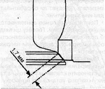
Check the width of the valve seat working chamfer, which should be 1.7 mm.
Assembly
Clean all parts before installation.
Warning: Be careful not to damage the valve seats.
Using special tool KM-J-38537, install the oil deflector caps onto the valve guide bushings.
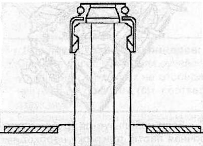
Notes:
- Do not reuse previously removed valve stem seals.
- Incorrect installation of the valve stem seal will adversely affect its working edge due to eccentricity and will result in engine oil leakage through the valve guide.
Apply a thin coat of engine oil to the valve stems and install the valves in their original positions in the cylinder head.
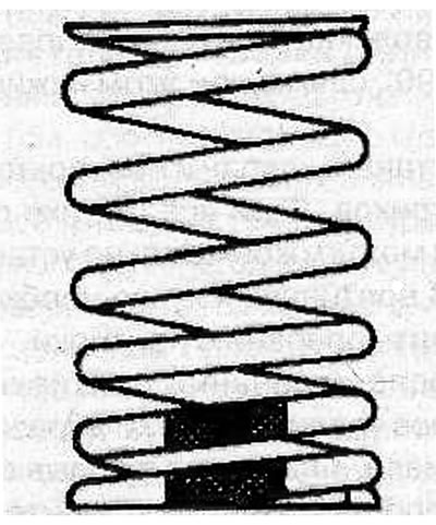
Install the valve spring and spring retainer with the painted end of the spring facing down.
Compress the spring using a special tool. Install the crackers and remove the special spring compressor.
Using a plastic hammer or hammer handle, tap the end of the valve stem several times to seat the crackers in place.
Install the valve lifters and adjusting washers.
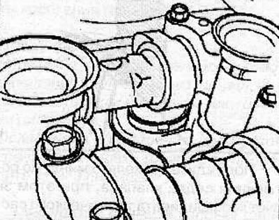
Install the camshafts (see the relevant chapter).
Screw in the spark plugs using a spark plug wrench. To avoid damaging the spark plug, install the key strictly along the spark plug axis.
Install the exhaust manifold (see the relevant chapter).
Installation
Install the cylinder head gasket onto the cylinder block and check that it is positioned correctly.
Install the cylinder head onto the cylinder block and tighten the new cylinder head mounting bolts in the sequence shown in the figure:
- 1st pass: tighten the bolts to 29 Nm;
- 2nd pass: tighten the bolts to 64 Nm.
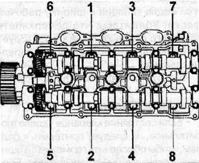
Warning: Use new cylinder head bolts.
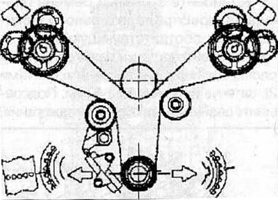
Install the timing belt of the gas distribution mechanism drive (see the relevant chapter).
For right cylinder head:
Install the front exhaust pipe (see the relevant chapter).
Install the bolts securing the guide tube for the engine oil level indicator to the cylinder head.
Install the exhaust gas recirculation pipe mounting bolts to the cylinder head and tighten them to 28 N·m.
For left cylinder head:
Install the power steering pump bracket and secure with 3 bolts (arrows), tightening them to a torque of 22 N·m.
Install the power steering pump (see the relevant chapter).
Install the front exhaust pipe (see the relevant chapter).
Install the coolant manifold and secure with bolts, tightening them to a torque of 22 N·m. Connect the coolant hoses and connectors to the manifold.
Install the fan pulley assembly onto the cylinder block and secure with bolts and nuts, tightening them to a torque of 24 N·m.
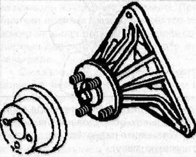
Install the radiator fan on the viscous coupling pulley and secure with nuts, tightening them to a torque of 10 Nm.
Install the radiator (see the relevant chapter).
Install the expansion air chamber (see the relevant chapter).
Install the accessory drive belt (see the relevant chapter).
Install the cylinder head cover and secure with bolts, tightening them to a torque of 9 Nm.
Install the ignition coils and secure with bolts, tightening them to a torque of 4 Nm.
Connect the cable to the negative terminal of the battery.
Visitor comments