


Removal
Remove the engine from the car (see the relevant chapter).
Place the engine on the stand.
Remove the cylinder head (see the relevant chapter).
Remove the crankcase (see the relevant chapter).
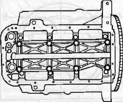
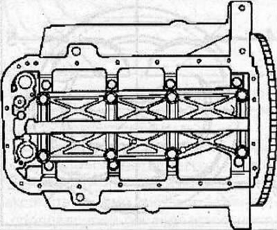
Remove 8 bolts and oil gallery.
Using metal feeler gauges, measure the side clearance between the lower connecting rod head and the crankshaft. If the side clearance exceeds 0.40 mm, replace the connecting rod.
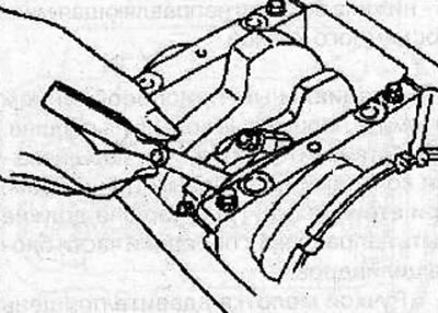
Check for steps or carbon deposits at the top of each cylinder. Using a special tool, remove the step at the top of the cylinders.
Warning: If the pistons are removed without removing the step at the top of the cylinder, damage to the piston rings and pistons may occur.
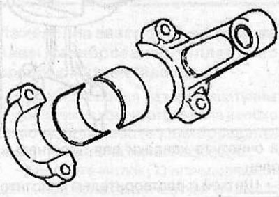
Loosen the bolts and remove the connecting rod caps.
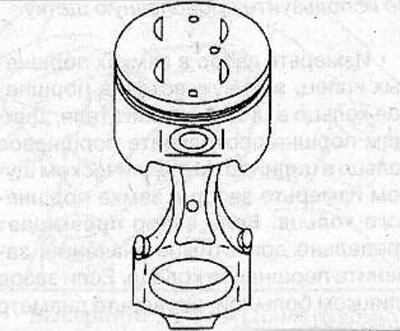
Use the hammer handle to push the piston and connecting rod out of the cylinder.
Notes:
- Keep the connecting rod bearing shells, connecting rod and cap together.
- Mark the pistons according to the cylinder numbers they were installed in.
Replacing the piston
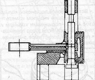
Using the KM-J-24086-C tool kit, press the piston pin out of the piston and connecting rod.
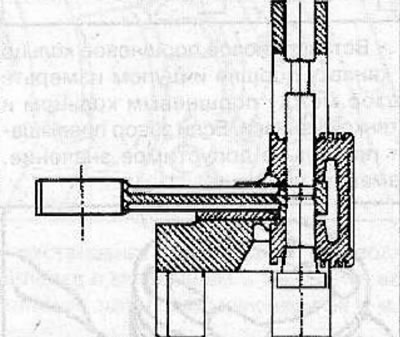
Note:
- To facilitate pressing out the piston pin, heat the piston to a temperature of 280°C.
- Store the piston, connecting rod and piston pin so that they can be reassembled to their original position.
Clean the piston
- Use a scraper to remove carbon deposits from the top of the piston.
- Use a special tool or a piece of a broken piston ring to clean the piston ring grooves.
- Use a brush and solvent to thoroughly clean the piston.
Check the pistons for cracks, scoring and excessive wear.
Measure the piston diameter at a distance of 45.0 mm from the piston crown in a plane perpendicular to the piston pin axis. The mark on the piston bottom indicates the outside diameter of the piston.
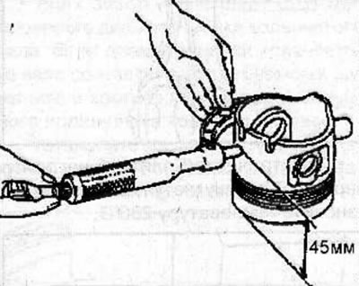
Piston outside diameter:
- mark A: 93.360-93.370 mm
- mark B: 93.371-93.380 mm
- mark C: 93.381-93.390 mm
Measure the diameter of each piston pin in two diametrically opposite directions and three planes.
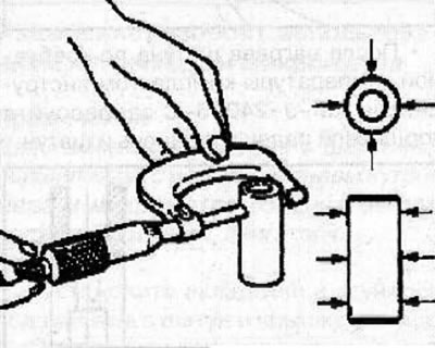
Measure the inside diameter of the small end of the connecting rod.
Determine the piston pin clearance in the connecting rod by subtracting the piston pin diameter from the connecting rod head bore diameter. If the clearance is more than 0.023-0.040 mm, replace the connecting rod and piston pin.
Measure the inside diameter of the bore in the piston.
Insert the piston pin into the piston and make sure it rotates easily and smoothly.
Determine the piston pin clearance by subtracting the piston pin diameter from the piston pin bore diameter. If the clearance exceeds 0.040 mm, replace the piston and piston pin.
There is a strip of thermal paint on the upper head of the connecting rod. When the required heating temperature of the connecting rod upper head is reached, the green color of the thermal paint changes to black. The strip of thermal paint (arrow) should not change color along its entire length, but only in the area of the upper connecting rod head.
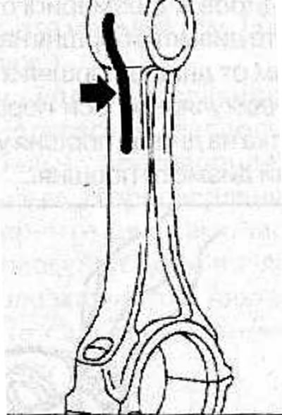
Using an electric hotplate, heat the upper connecting rod head, setting the temperature to 280°C.
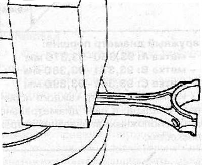
After heating the connecting rod to the required temperature, use the KM-J-24086-C tool kit to press the piston pin into the piston and connecting rod.
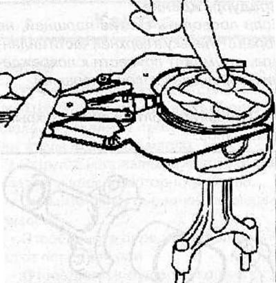
Removal and installation piston rings
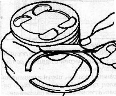
Using special pliers (1), remove the piston rings from the piston.
Use a special tool or a piece of a broken piston ring to clean the piston ring grooves.
Clean the piston with a brush and solvent.
Note: Do not use a wire brush.
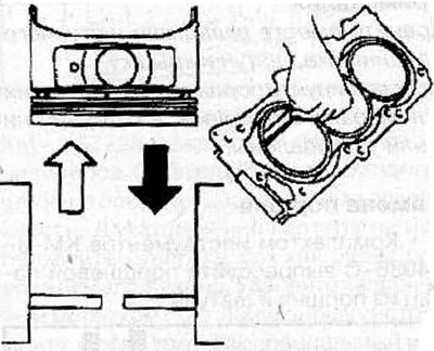
Measure the piston ring gap by manually inserting a piston ring into the engine cylinder. Use the bottom of the piston to push the piston ring into the cylinder. Use a metal feeler gauge to measure the gap in the piston ring joint. If the clearance exceeds the maximum permissible value, replace the piston ring. If the gap is too large, check the cylinder diameter.
Insert a new piston ring into the piston groove and use a feeler gauge to measure the gap between the piston ring and the groove wall. If the clearance exceeds the maximum permissible value, replace the piston.
Install the expander, upper and lower side guides of the oil scraper ring (A) on the piston.
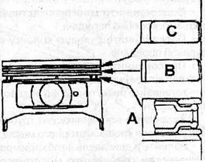
Install the second compression ring (B) onto the piston, with the 2T mark on the ring facing upwards.
Install the first compression ring (C) onto the piston, with the T mark on the ring facing upwards.
Installation
Lubricate the piston and piston rings with engine oil.
Make sure the piston ring seals are properly positioned on the piston.
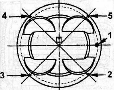
1 - mark on the piston, directed towards the front of the cylinder block; 2 - compression ring lock 1; 3 - upper side guide of the oil scraper ring; 4 - compression ring lock 2; 5 - lower side guide of the oil scraper ring
Using a special tool, compress the piston rings onto the piston.
Install the piston with piston rings over the first cylinder, with the mark (1) on the piston facing the front of the cylinder block.
Use the hammer handle to push the piston into the cylinder. After the piston and connecting rod have come out of the special device, before installing the piston in place, make sure that the connecting rod is correctly aligned with the crankshaft journal.
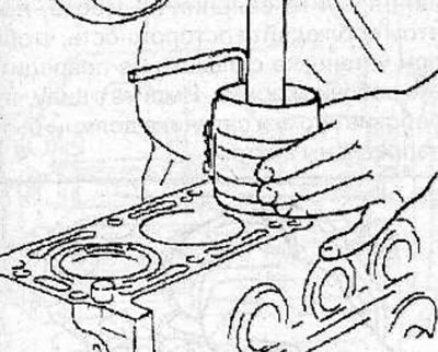
Warning! When installing pistons, press a special device for compressing piston rings firmly against the cylinder block, which will prevent the piston rings from expanding before they enter the cylinder.
Lubricate the working surfaces of the new connecting rod bearing shells with engine oil and install them into the connecting rods and connecting rod caps.
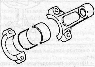
Install the connecting rod caps onto the connecting rods and secure with new bolts, tightening them to a torque of 54 N·m.
Turn the crankshaft and make sure it rotates easily and smoothly.
Install the oil gallery and secure with new bolts, tightening them in the specified sequence as follows:
- 1st pass: tighten the bolts to 29 Nm;
- 2nd pass: tighten the bolts to an angle of 55-65°.
Install the crankcase on the cylinder block and secure with bolts, tightening them to a torque of 10 Nm.
Install the cylinder head (see the relevant chapter).
Remove the engine from the stand.
Visitor comments