


Contents: Removal ⬇ Replacing the piston ⬇ Removal and installation piston rings ⬇ Measuring clearances in crankshaft…⬇ Installation ⬇
Removal
Remove the engine from the car (see the relevant chapter).
Install the engine on the KM-412 stand with KM-412-8-1-2 adapters.
Remove the cylinder head (see the relevant chapter).
Remove the balance shaft assembly (see the relevant chapter).
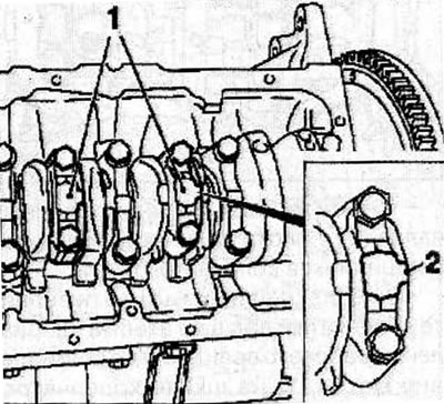
Place marks on the connecting rod caps (1) so that the marks (2) are located on the flywheel side.
Remove the bolts and the connecting rod caps.
Check for steps or carbon deposits at the top of each cylinder. Using a special tool, remove the step at the top of the cylinders.
Warning: If the pistons are removed without removing the step at the top of the cylinder, damage to the piston rings and pistons may occur.
Use a wooden block or a hammer handle to push the piston and connecting rod out of the cylinder.
Notes:
- Keep the connecting rod bearing shells, connecting rod and cap together.
- Mark the pistons according to the cylinder numbers they were installed in.
Replacing the piston
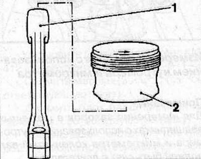
Note: Pressing out the piston pin from the piston and connecting rod is prohibited. If the piston, piston pin or connecting rod (1) is damaged or worn, replace these parts as a set.
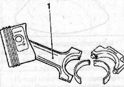
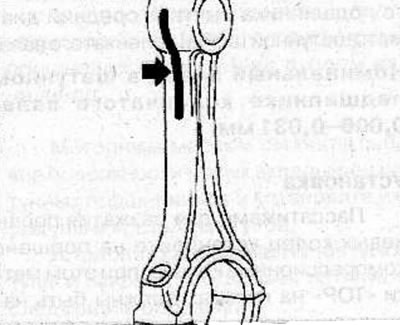
There is a strip of thermal paint on the upper head of the connecting rod. When the required heating temperature of the connecting rod upper head is reached, the green color of the thermal paint changes to black. The strip of thermal paint (arrow) should not change color along its entire length, but only in the area of the upper connecting rod head. Use a heater to heat the upper connecting rod head, setting the heater temperature to 280-320°C.
Warning! Piston pin installation position: The lugs on the connecting rod and connecting rod cap (arrows) must be located on the chamfer side (arrow) on the piston pin.
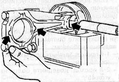
Note: Once pressed in, the piston pin cannot be pressed in further, so assembly must be done very quickly.
After heating the connecting rod to the required temperature, install the piston (2) on the connecting rod (1) and press in the new piston pin until it stops in the piston.
Removal and installation piston rings
Original source on the website: www.OpelBook.ru
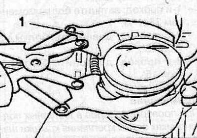
Using special pliers (1), remove the piston rings from the piston.
Using a special tool or a piece of broken piston ring, clean the piston ring grooves.
Clean the piston with a brush and solvent.
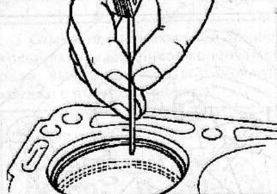
Measure the piston ring gap by manually inserting a piston ring into the engine cylinder. Use the bottom of the piston to push the piston ring into the cylinder. Use a feeler gauge to measure the gap in the piston ring joint. If the clearance exceeds the maximum permissible value, replace the piston ring. If the gap is too large, check the cylinder diameter.
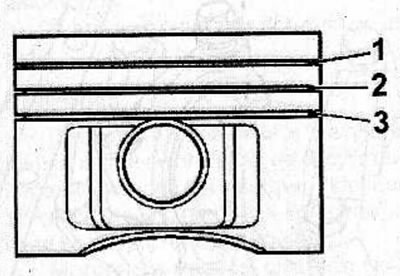
Piston ring gap;
- first compression ring (1): 0.30-0.50 mm.
- second compression ring (2): 0.30-0.50 mm.
- oil scraper ring (3): 0.40-1.40 mm.
Insert a new piston ring into the piston groove and use a feeler gauge to measure the gap between the piston ring and the groove wall. If the clearance exceeds the maximum permissible value, replace the piston.
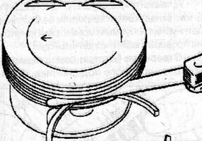
Clearance between piston ring and piston groove:
- first compression ring: 0.02-0.040 mm.
- second compression ring: 0.02-0.040 mm.
- oil scraper ring: 0.01-0.03 mm.
Measuring clearances in crankshaft connecting rod bearings
Measuring gaps using a calibrated plastic rod Plastigage
To measure the clearance in the crankshaft connecting rod bearings, it is necessary to use a calibrated plastic Plastigage rod.
Apply marks (1) to determine the relative positions of the connecting rod and connecting rod cap.
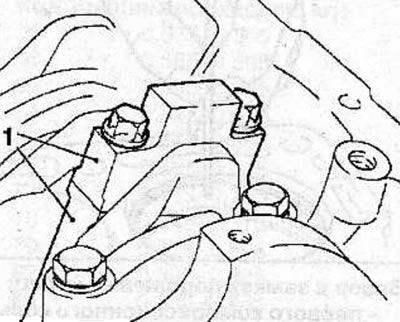
Remove the bolts and cover and connecting rod bearing shell. Clean the bearing, cover and crankshaft journal.
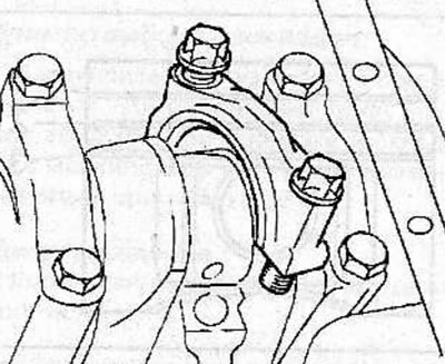
Cut a piece of Plastigage plastic gauge rod the same length as the bearing width and place it along the crankshaft axis on the connecting rod bearing journal.
Install the connecting rod bearing cap with the liner and secure it with bolts, tightening them to the required torque. Do not turn the crankshaft while doing this.
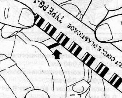
Loosen the bolts and remove the connecting rod bearing cap again. Compare the width of the deformed Plastigage plastic rod with the measuring scale printed on the plastic rod packaging. Use the scale to determine the gap.
- Nominal clearance in the crankshaft connecting rod bearing: 0.006-0.031 mm.
- Maximum permissible clearance in the crankshaft connecting rod bearing: 0.12 mm.
If the clearance exceeds the permissible value, replace the crankshaft connecting rod bearing shells as a set.
Install the connecting rod cap onto the connecting rod and secure with bolts, tightening them as follows:
- 1st pass: tighten the bolts to 35 Nm;
- 2nd pass: tighten the bolts to an angle of 45°;
- 3rd pass: tighten the bolts by an additional 15°.
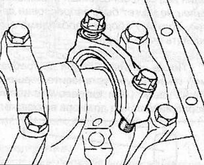
Measuring clearances using a bore gauge and micrometer
Note: To measure connecting rod bearing clearances using a bore gauge and micrometer, the crankshaft must be removed from the engine.
Install the connecting rod bearing shells into the connecting rod and connecting rod cap.
Install the connecting rod cap onto the connecting rod and secure with bolts, tightening them as follows:
- 1st pass: tighten the bolts to 35 Nm;
- 2nd pass: tighten the bolts to an angle of 45°;
- 3rd pass: tighten the bolts by an additional 15°.
Note: When checking connecting rod bearing clearances, the connecting rod cap bolts can be used multiple times.
Using a bore gauge, measure the inside diameter of the crankshaft connecting rod bearing.
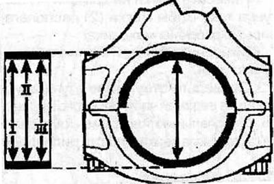
Calculate the average diameter of the connecting rod bearing bore using the formula: Average diameter of the connecting rod bearing bore = (I + II + III): 3
Example:
- I = 42.738 mm
- II = 42.732 mm
- III = 42.741 mm
Average bore diameter of connecting rod bearing = (42.738 + 42.732 + 42.741): 3 = 42.737 mm
Using a micrometer, measure the diameter of the crankshaft connecting rod journal in two diametrically perpendicular planes.
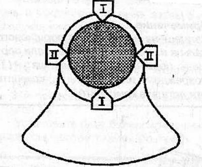
Calculate the average diameter of the crankshaft journal using the formula:
Average diameter of crankshaft journal = (I + II): 2
Example:
- I = 42.729 mm
- II = 42.725 mm
Average diameter of crankshaft journal = (42.729 + 42.725): 2 = 42.727 mm
Calculate the clearance in the crankshaft connecting rod bearing by subtracting the average diameter of the crankshaft connecting rod journal from the average diameter of the connecting rod bearing bore. Nominal clearance in the crankshaft connecting rod bearing: 0.006-0.031 mm
Installation
Using piston ring pliers, install the compression rings onto the piston, with the "TOP" marks on the rings facing upwards.
Position the locks of the upper and lower compression (I) rings at an angle of 180°.
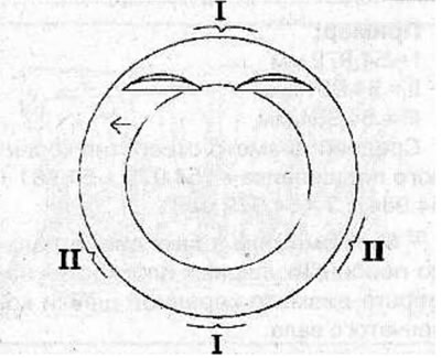
Position the oil scraper ring lock (II) with an offset of 25-50 mm to the left of the expansion ring lock.
Lubricate the piston and piston rings with engine oil. Install the piston with piston rings over the first cylinder, with the arrow (1) on the piston pointing towards the front of the cylinder block and the mark on the connecting rod facing the flywheel. Using a special tool, compress the piston rings onto the piston.
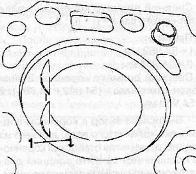
Use the hammer handle to push the piston into the cylinder. After the piston and connecting rod have come out of the special device, before installing the piston in place, make sure that the connecting rod is correctly aligned with the crankshaft journal.
Warning! When installing pistons, press a special device for compressing piston rings firmly against the cylinder block, which will prevent the piston rings from expanding before they enter the cylinder.
Lubricate the working surfaces of the new connecting rod bearing shells with engine oil and install them into the connecting rods and connecting rod caps.
Install the connecting rod caps onto the connecting rods and secure with bolts, tightening them as follows:
- 1st pass: tighten the bolts to 35 Nm;
- 2nd pass: tighten the bolts to an angle of 45°;
- 3rd pass: tighten the bolts by an additional 15°.
Install the balance shaft block (see the relevant chapter).
Install the cylinder head (see the relevant chapter).
Remove the engine from the KM-412 stand and remove the adapters from the KM-412-8-1-2 from the engine.
Install all previously removed components onto the engine.
Install the engine (see the relevant chapter).
Visitor comments