


Contents: Checking the play ⬇ Backlash adjustment ⬇
Checking the play
Remove the oil pan (see the relevant chapter).
Disconnect the oil pick-up pipe (1) from the oil pump and balance shaft block.
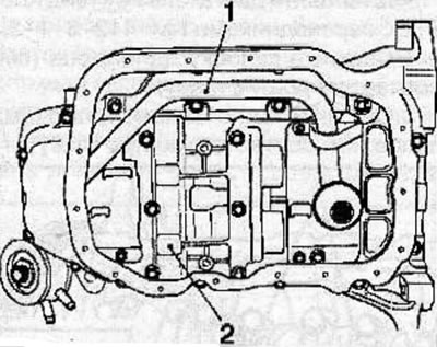
Remove the balance shaft assembly (2) from the cylinder block and crankshaft bearing caps.
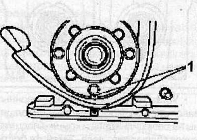
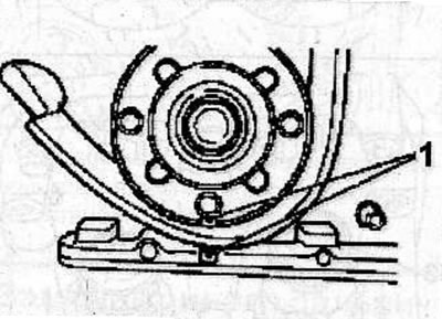
Using the pulley mounting bolt, turn the engine crankshaft in the direction of working rotation until the mark (1) on the crankshaft pulley aligns with the mark on the front cover of the cylinder block, while the piston of the 1st cylinder is set to TDC in the compression stroke.
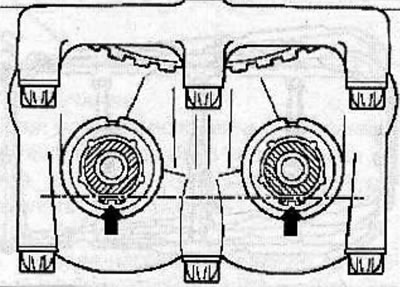
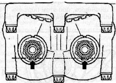
Make sure the holes (arrows) in the washers on the balance shafts are facing down and are horizontally aligned.
Fasten the clamp (3) of the special tool KM-949 with a long screw with a knurled head (1) to the 1st balancing shaft (from the inlet side) and tighten the screw so that the measuring lever (5) is set to the 9 o'clock position.
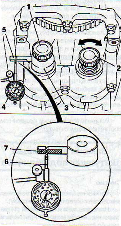
Screw the second knurled head screw (2) into the 2nd balance shaft (from the outlet side) and tighten it securely.
Install the KM-798 pointer-type indicator support (4) on the cylinder block, then install the measuring tip (6) of the indicator on the measuring lever of the KM-949 special tool. The measuring tip of the pointer-type indicator must be installed exactly between the two marks perpendicular to the plane (7) of the measuring lever.
The measurement must be carried out by turning the knurled screw (2) clockwise and then counterclockwise. Set the pointer indicator arrow to zero.
By turning the knurled screw clockwise and then counterclockwise on the dial indicator scale, determine the play of the balance shaft gears.
Allowable clearance: 0.02-0.06 mm
The clearance must be measured in four different positions, for which purpose turn the engine crankshaft clockwise by 45° each time using the pulley mounting bolt until the measuring lever (2) is set to the 6 o'clock position. Then loosen the knurled screw (3), turn the measuring lever to the 9 o'clock position, tighten the screw and measure the clearance of the gears. Take the measurement by turning the knurled screw (1) clockwise and then counterclockwise.
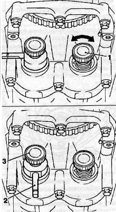
If the play is outside the range of 0.02-0.06 mm in any of the 4 measurements, adjust it.
Backlash adjustment
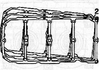
Remove the balance shaft assembly together with the gasket from the cylinder block and crankshaft bearing caps. There is a marking on the gasket that determines the thickness of the gasket. The clearance can be adjusted by installing a shim of appropriate thickness.
| Code | Thickness of gaskets, mm |
| 55 | 0,535-0,565 |
| 58 | 0,565-0,595 |
| 61 | 0,595-0.625 |
| 64 | 0,625-0,655 |
| 67 | 0,655-0,685 |
| 70 | 0,685-0,715 |
| 73 | 0,715-0,745 |
| 76 | 0,745-0,775 |
| 79 | 0,775-0,805 |
| 82 | 0,805-0,835 |
| 85 | 0,835-0,865 |
Note: Installing a thinner or thicker shim changes the clearance by 0.02 mm.
Example of choosing a gasket
With the gasket marked "70" installed, the measured play was 0.08 mm. When installing the gasket marked "67", the play should be approximately 0.06 mm.
Warning! Only one gasket should be installed.
Using the pulley mounting bolt, turn the engine crankshaft in the direction of working rotation until the mark (1) on the crankshaft pulley aligns with the mark on the front cover of the cylinder block, while the piston of the 1st cylinder is set to TDC in the compression stroke.
Turn the balance shafts so that the holes (arrows) in the washers on the balance shafts are at the bottom and are horizontally aligned.
Install the balance shaft block with a gasket (2) of the selected thickness on the cylinder block and crankshaft bearing caps. Tighten the balance shaft block mounting bolts:
- 1st pass: 20 Nm;
- 2nd pass: tighten the bolts to an additional 45° angle.
Check the balance shaft gear play and readjust if necessary.
Note: When replacing the balance shaft assembly, the thickest gasket marked "85" should be installed first, this will provide some play under all conditions.
Install the oil pick-up tube with a new sealing ring onto the oil pump and secure with bolts, tightening them to a torque of 8 N·m, having first applied a locking agent to the bolt threads.
Install the oil pickup tube bracket onto the balance shaft block and secure with bolts. Tighten the M6 bolts to a torque of 10 Nm and the M8 bolts to a torque of 20 Nm.
Install the oil pan (see the relevant chapter).
Visitor comments