


Contents: Removal ⬇ Installation ⬇
The valve timing components are installed and operate in the cylinder head. To improve thermal conductivity and reduce weight, the cylinder head is made of light alloy. It is exposed to high temperatures and gas pressures and therefore has a rigid lower support surface and is intensively cooled by liquid, and the wall thickness is made as uniform as possible to reduce internal stresses from thermal expansion. The valve seats are pressed into the cylinder head. Each combustion chamber has threaded holes for spark plugs. The threads in the holes can be damaged if the spark plug is tightened too much or is screwed in at an angle.
Warning! To avoid damaging the cylinder head due to temperature changes, remove the cylinder head on a cold engine.
Removal
Disconnect the cable from the negative battery terminal.
Disconnect the connector from the engine air temperature sensor located on the air intake tube (1).
Disconnect the resonator hose from the air intake tube (1).
Remove the air intake tube (1) and the air filter housing cover (2) as an assembly.
Disconnect the air intake tube bracket and ground wire from the cylinder head.
Remove the lower engine compartment protection.
Drain the coolant from the engine cooling system.
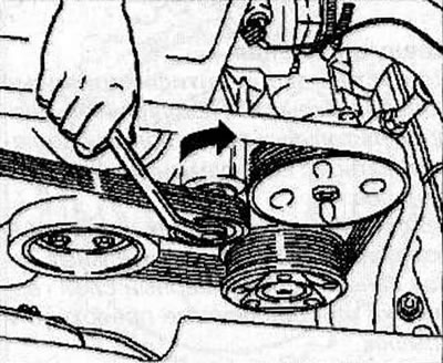
Mark the direction of rotation of the V-belt.
Using a spanner (KM-913-A), turn the belt tensioner roller clockwise by the mounting bolt, thereby loosening the belt tension, and remove the auxiliary drive V-belt.
Disconnect the upper hose from the radiator.
Disconnect the front exhaust pipe from the exhaust manifold.
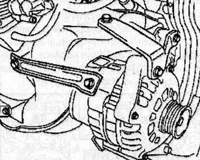
Remove the generator (see the relevant chapter).
Disconnect the connector from the crankshaft position sensor.
Disconnect the connector from the knock sensor.
Disconnect the hose from the heater on the coolant inlet side.
Disconnect the hose from the heater on the coolant outlet side.
Disconnect the cooling system hoses from the throttle body.
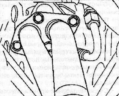
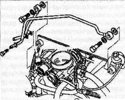
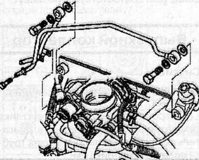
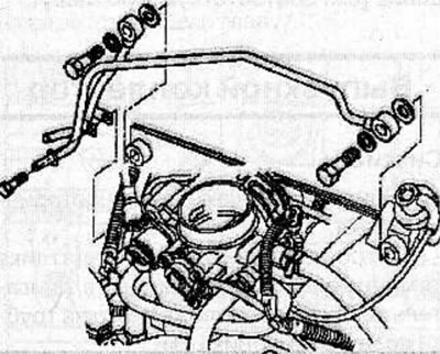
Remove the hollow bolts and disconnect the fuel lines from the fuel rail, then remove the fuel line bracket along with the ground wire.
Disconnect the connector from the fuel tank vent solenoid valve.
Disconnect the vacuum hose from the canister (activated carbon canisters).
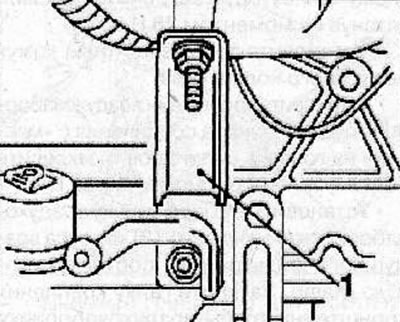
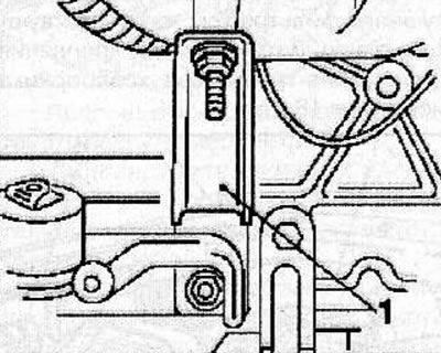
Disconnect the support (1) from the intake manifold and cylinder block.
Remove the bolts securing the coolant pipe to the intake manifold.
Remove the front timing belt cover (see the relevant chapter).
Disconnect the connector from the power steering pump pressure sensor.
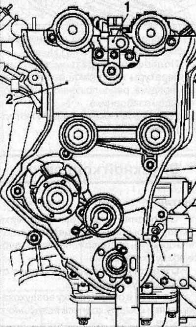
Disconnect the camshaft position sensor connector (1).
Remove the rear cover (2) of the timing belt (see the relevant chapter).
Disconnect the connector from the engine oil pressure sensor.
Remove the exhaust side camshaft from the cylinder head (see the relevant chapter).
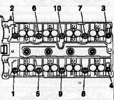
In a certain sequence, loosen the cylinder head mounting bolts first by a quarter, then by half a turn and unscrew the bolts.
Warning! Failure to remove the bolts in the correct sequence may result in deformation or cracking of the cylinder head.
Remove the cylinder head together with the intake camshaft from the cylinder block guide pins and place it on the blocks on the work bench.
Clean the mating surfaces of the head and cylinder block from any gasket residue.
Warning: Be careful not to damage the mating surfaces of the cylinder head and block.
Installation
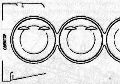
Install the cylinder head gasket onto the cylinder block with the "OBEN/TOP" identification mark facing up at the front of the engine.
In a certain sequence, in several passes, using special tools KM-2355, MKM-610 and KM-470-V, tighten the new cylinder head mounting bolts:
- 1st pass: tighten the bolts to 25 Nm;
- 2nd pass: tighten the bolts to an angle of 90°;
- 3rd pass: tighten the bolts to an angle of 90°;
- 4th pass: tighten the bolts to an angle of 90°.
Install the exhaust camshaft (see the relevant chapter).
Connect the connector to the engine oil pressure sensor.
Install the rear timing belt cover for the gas distribution mechanism (see the relevant chapter).
Connect the connector to the camshaft position sensor.
Connect the connector to the power steering pump pressure sensor.
Install the front timing belt cover (see the relevant chapter).
Install the coolant pipe to the intake manifold.
Install the intake manifold support (1) and secure with bolts, tightening them to a torque of 22 Nm.
Connect the vacuum hose to the canister (canister with activated carbon).
Connect the connector to the fuel tank vent solenoid valve.
Connect the fuel lines to the fuel rail and secure them with the hollow bolts, tightening them to a torque of 25 N·m, then install the fuel line bracket together with the ground wire and secure them with the bolts, tightening them to a torque of 25 N·m.
Connect the cooling system hoses to the throttle body.
Connect the hose to the heater on the coolant outlet side.
Connect the hose to the heater from the coolant inlet side.
Connect the connector to the knock sensor.
Connect the connector to the crankshaft position sensor.
Install the generator (see the relevant chapter).
Connect the front exhaust pipe with a new gasket to the exhaust manifold and secure with nuts, tightening them to a torque of 28 N·m.
Connect the top hose to the radiator.
Install the V-belt (see the relevant chapter).
Install the lower engine compartment protection.
Install the air intake pipe bracket and ground wire to the cylinder head and secure with the bolt, tightening it to a torque of 22 N·m.
Install the air intake tube (1) and air filter housing cover (2) as an assembly (see the relevant chapter). Tighten the air intake pipe bracket mounting nut to 16 N·m.
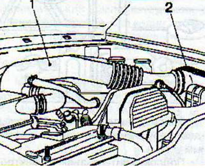
Connect the resonator hose to the air intake tube (1).
Connect the connector to the engine air temperature sensor located in the air intake pipe.
Fill the engine cooling system with coolant and check the cooling system for leaks (see the relevant chapter).
Visitor comments