


Warning! To avoid damaging the cylinder head due to temperature changes, remove the head on a cold engine.
Removal
Disconnect the cable from the negative battery terminal.
Set the piston of the 1st cylinder to TDC in the compression stroke (see the relevant chapter).
Remove the lower engine compartment protection.
Disconnect the front exhaust pipe from the turbocharger.
Loosen the lower generator mounting bolt.
Disconnect the cooling system hose (1) from the generator bracket and move it to the side.
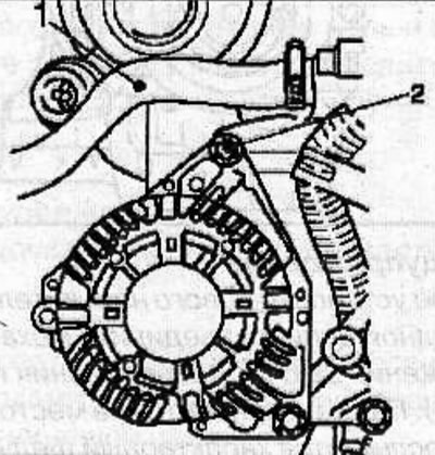
Remove the upper generator mounting bolt (2), then tilt the generator downwards by turning it on the lower generator mounting bolt.
Disconnect the turbocharger feed (1) and return (5) oil lines from the cylinder block. To collect any leaking engine oil, place a suitable container under the cylinder block.
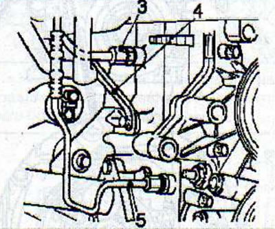
Disconnect the support bracket (4) from the exhaust manifold and cylinder block.
Drain the coolant from the engine cooling system.
Disconnect the charge air intercooler hose from the upper section of the intake manifold and move it to the side.
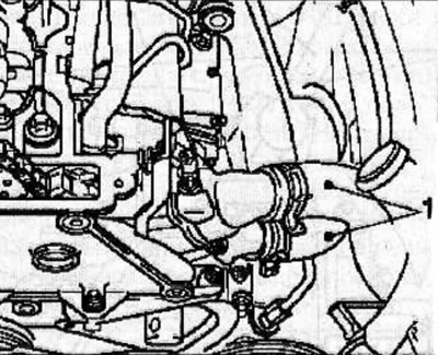
Disconnect the cooling system hoses (1) from the thermostat housing.
Disconnect the vacuum hose (1) from the EGR valve.
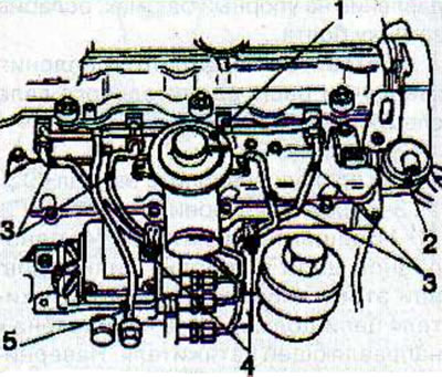
Mark the installation position and remove the clamps (4) securing the high-pressure fuel pipes.
Disconnect the high-pressure fuel pipes (3) from the fuel injectors and the high-pressure fuel pump.
Warning! Immediately after disconnecting the high-pressure pipes, be sure to plug any openings through which contaminants may enter the fuel system.
Using special pliers KM-717, disconnect the connectors from the glow plugs and move them to the side.
Disconnect the bypass pipe (5).
Disconnect the vacuum hose (2) from the diaphragm valve of the exhaust gas re-combustion system.
Mark the installation position and remove the single-row chain tensioner (1).
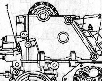
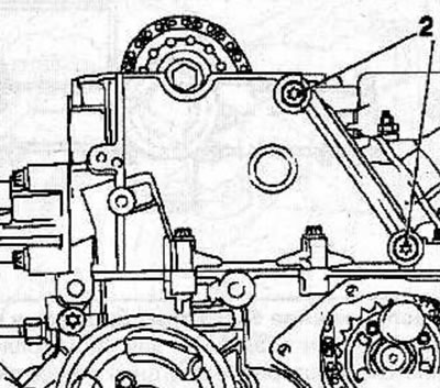
Heat the bolts (2) for fastening the single-row chain guide with a hair dryer and unscrew them.
Mark the installation position and remove the single-row chain guide by lifting it upwards.
Remove the measuring tool KM-932 from the cylinder head and remove the thrust pin KM-927 from the fuel injection pump pulley hole.
Remove the camshaft sprocket mounting bolt, holding the shaft by the hexagon with a wrench to prevent it from turning.
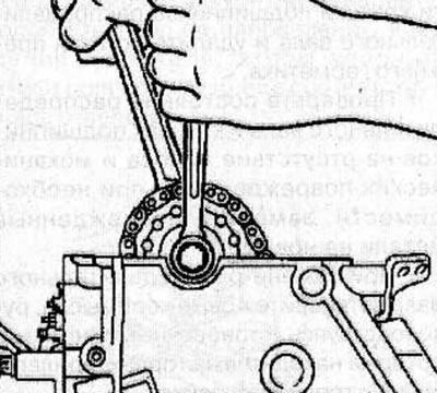
Secure the single-row chain to the timing case so that it does not fall into the case.
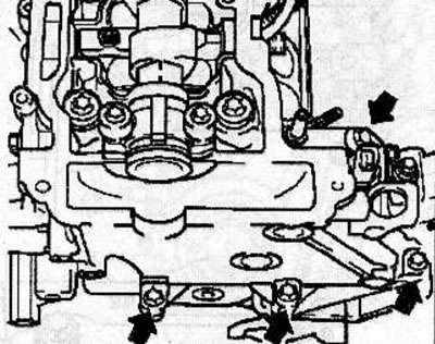
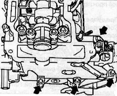
Remove the bolts (arrows), while marking their location, as the bolts are of different lengths.
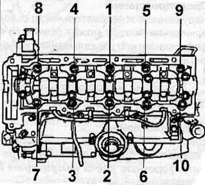
Loosen the cylinder head bolts in the sequence shown in the figure, first by a quarter, then by half a turn, and unscrew them.
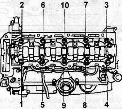
Warning! Failure to remove the bolts in the correct sequence may result in deformation or cracking of the cylinder head.
Carefully remove the cylinder head.
Warning! Place the removed cylinder head on wooden blocks to avoid damaging the injectors, glow plugs and valves.
Cover the engine cylinders with a clean, lint-free cloth.
Clean the mating surfaces of the head and cylinder block from any gasket residue.
Warning: Be careful not to damage the mating surfaces of the cylinder head and block.
Checking the cylinder head
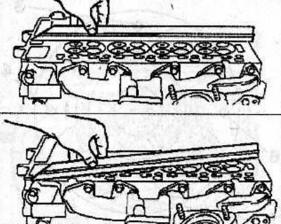
Using a metal ruler and feeler gauge, check the flatness of the cylinder head surfaces in several directions.
Measure the height (I) of the cylinder head.
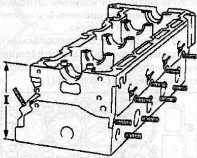
Cylinder head height: 140 mm
Installation
To select a gasket of the required thickness, measure the protrusion of the pistons from the cylinders.
Warning: Measure the protrusion of each piston individually.
Install the KM-301 measuring stand (2) on the cleaned surface of the cylinder block and install the MKM-571-V pointer-type indicator (1) to measure the piston protrusion.
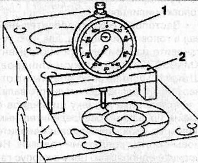
Set the pointer indicator arrow to zero.
Check the protrusion of all four pistons from the cylinder block.
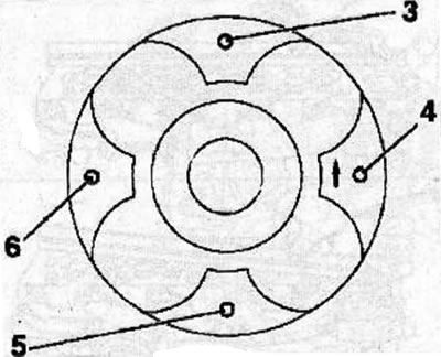
Measure the protrusion of each piston at two points (3 and 4) or (5 and 6), moving the stand with the pointer-type indicator accordingly and rotating the crankshaft, determine the maximum value of the protrusion.
After determining the thickness of the cylinder head gasket, fix the crankshaft with the KM-929 thrust pin, setting the piston of the 1st cylinder to TDC in the compression stroke.
Depending on the maximum piston protrusion, select the thickness of the gasket, which is identified by the number of notches (1).
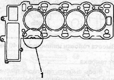
Table for selecting cylinder head gasket thickness depending on piston protrusion
| Piston protrusion, mm | Gasket thickness, mm | Number of notches |
| 0,40-0,50 | 1,2 | No |
| 0,51-0,60 | 1,3 | 1 |
| 0,61-0,70 | 1,4 | 2 |
Install a new cylinder head gasket of the selected thickness onto the cylinder head.
Lock the camshaft in the cylinder head by installing the KM-932 measuring tool (3) on the cylinder head. The pin (2) must be located in the hole (1) of the camshaft.
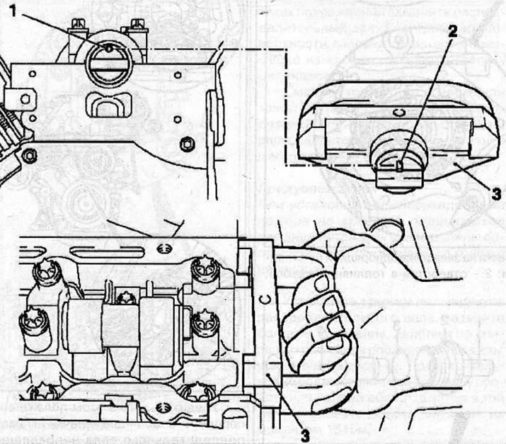
Installing the measuring tool KM-932 (3) on the cylinder head, while the pin (2) should be located in the hole (1) of the camshaft.
Install the cylinder head with the camshaft fixed on the cylinder block and screw in new head mounting bolts. Do not drop the single row chain into the timing case.
In a certain sequence, in several passes, tighten the new cylinder head mounting bolts with the special KM-470-V tool:
- 1st pass: tighten the bolts to 25 Nm;
- 2nd pass: tighten the bolts to an angle of 65°;
- 3rd pass: tighten the bolts to an angle of 65°;
- 4th pass: tighten the bolts to an angle of 65°;
- 5th pass: tighten the bolts to an angle of 65°;
- 6th pass: tighten the bolts by an additional 15°.
Install the timing drive housing onto the cylinder block and secure with bolts, tightening them evenly to a torque of 20 Nm.
Place a single row chain on the camshaft sprocket and secure the sprocket to the camshaft by screwing in and hand tightening a new bolt.
Install the guide (1) of the single-row chain in accordance with the previously applied marks.
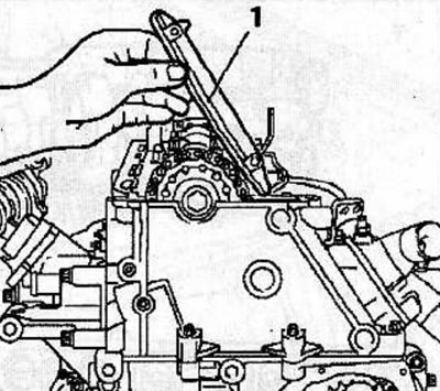
Using new bolts (2), secure the single-row chain guide and tighten the bolts to 8 Nm.
Make sure that the arrow (1) on the sprocket of the single-row high-pressure fuel pump (HPFP) drive chain matches the slot on the HPFP flange and the corresponding hole (2) in the fuel pump.
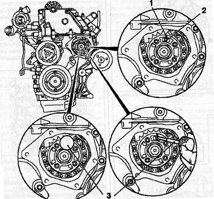
Setting the valve timing: 1 - arrow on the sprocket of the single-row high-pressure fuel pump drive chain; 2 - hole in the fuel pump; 3 - thrust pin KM-927.
Fix the fuel injection pump in this position by inserting the KM-927 stop pin (3) into the fuel injection pump hole.
Remove the lifting eyes from the cylinder head.
Install the thrust shoe (1) of the adjusting device (4) KM-933 into the hole of the camshaft sprocket. Secure the KM-933 tool to the cylinder head.
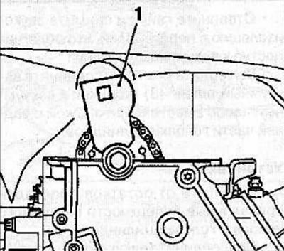
Insert the handle (2) into the hole in the stop shoe and gently push it in the direction of the arrow (in the direction opposite to the direction of rotation of the engine parts) and fix the shoe in this position with the clamping bolt (3).
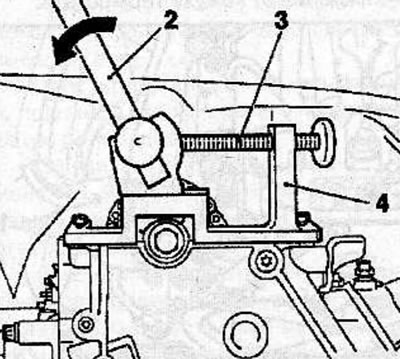
Make sure that the KM-927 thrust pin moves freely in the hole, otherwise, relieve the pressure on the thrust shoe by loosening the bolt,
Tighten the new camshaft sprocket bolt as follows:
- 1st pass: 90 Nm;
- 2nd pass: turn to an angle of 60°;
- 3rd pass: turn to an angle of 30°.
Install the single-row chain tensioner (4) into the cylinder head with the closed side of the chain tensioner facing the tensioner guide. Screw on the cover (2) with a new sealing ring (3) and tighten it to a torque of 60 Nm.
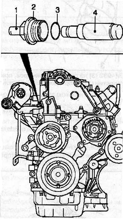
Remove all special adjustment devices.
Using the vibration damper mounting bolt, turn the crankshaft in the direction of engine rotation so that the TDC mark of the 1st cylinder piston (3) on the vibration damper is positioned opposite the mark (2) on the rear casing of the timing drive.
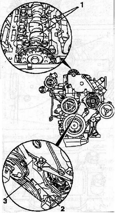
Make sure that in this position of the piston of the 1st cylinder, the camshaft cams (1) are directed upwards.
To prevent the crankshaft from turning, insert the KM-929 stop pin (1) into the hole for the crankshaft position sensor. If necessary, carefully turn the crankshaft in the direction of engine rotation until the thrust pin is fully seated in the corresponding hole.
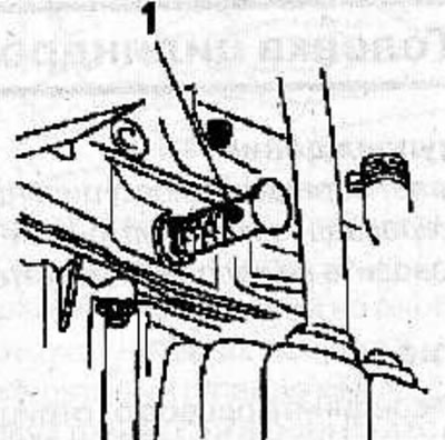
Make sure that after fixing the crankshaft, the timing marks (3) are opposite each other.
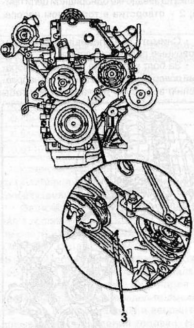
Make sure that the arrow (1) on the sprocket of the single-row high-pressure fuel pump (HPFP) drive chain matches the slot on the HPFP flange and the corresponding hole (2) in the fuel pump.
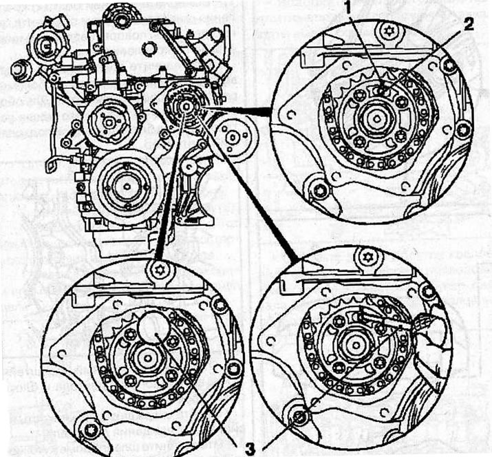
Setting the valve timing: 1 - arrow on the sprocket of the single-row high-pressure fuel pump drive chain; 2 - hole in the fuel pump; 3 - thrust pin KM-927.
Fix the fuel injection pump in this position by inserting the KM-927 stop pin (3) into the fuel injection pump hole.
Install the measuring tool KM-932 (3) on the cylinder head.
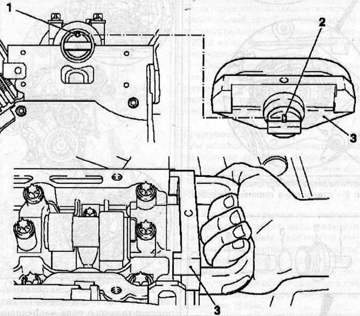
Installing the measuring tool KM-932 (3) on the cylinder head, while the pin (2) should be located in the hole (1) of the camshaft.
The pin (2) must be located in the hole (1) of the camshaft.
Remove all tools used to check the valve timing.
Warning: High pressure fuel lines are intended to be used only once, so use new lines when installing.
Connect the high-pressure fuel pipes to the fuel rail and the high-pressure fuel pump and secure them with the union nuts, tightening them to a torque of 25 N·m.
Install the high pressure fuel line clamps.
Install a new sealing gasket (1) into the special groove (2) located between the cylinder head cover and the bushing.
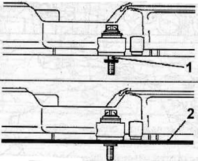
Apply sealant to the cylinder head cover (arrows), install the cover with a new gasket on the cylinder head and secure with bolts, tightening them to a torque of 8 Nm.
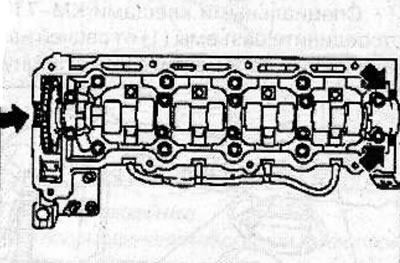
Warning: Install the cylinder head cover within 10 minutes after applying the sealant.
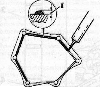
Apply approximately 2 mm of sealant (I) to the protective cover, install the cover and secure with the bolts, tightening them to a torque of 6 Nm.
Install engine lifting eyes on the cylinder head.
Install the crankshaft angle sensor bracket to the lower portion of the intake manifold.
Secure the wiring harness to the top of the intake manifold and connect the connectors.
Connect the coolant hose to the cylinder head.
Connect the vacuum hose to the cylinder head cover.
Connect the vacuum hose to the diaphragm valve of the exhaust gas re-combustion system.
Connect the bypass pipe.
Connect the charge air intercooler hose to the upper section of the intake manifold.
Connect the cooling system hoses to the thermostat housing.
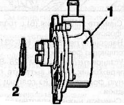
Install the vacuum pump (1) with a new sealing ring (2) (see the relevant chapter).
Install the wiring harness bracket to the rear right side of the engine.
Connect the brake booster vacuum hose to the vacuum pump.
Connect the connectors to the glow plugs and secure the wiring harness to the cylinder head cover.
Connect the oil feed pipe with new seals to the turbocharger, but do not tighten the pipe mounting union nut.
Connect the charge air cooler hose to the turbocharger.
Install the top mounting bracket of the generator / cooling system hose and fasten it with bolts, tightening them to a torque of 35 Nm.
Install the generator to the upper mounting bracket and coolant hose.
Connect the vacuum hose to the turbocharger valve actuator.
Connect the air intake tubes to the air filter and turbocharger and secure them to the top of the engine.
Connect the connector to the air flow meter.
Tighten the lower generator mounting bolt to 35 N·m.
Connect the turbocharger oil supply pipe to the cylinder block and secure it with the union nut, tightening it to a torque of 20 Nm.
Install the support bracket onto the exhaust manifold and cylinder block and secure with bolts, tightening them to a torque of 25 Nm.
Install the crankshaft angle sensor with a new sealing ring onto the cylinder block.
Install the automatic V-belt tensioner onto the bracket and secure with bolts, tightening them to a torque of 42 Nm.
Install the vibration damper onto the automatic V-belt tensioner and secure with the bolt, tightening it to a torque of 23 Nm.
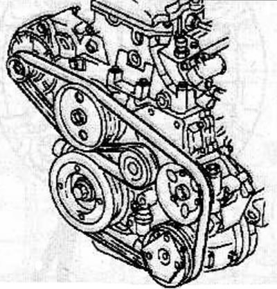
Place the accessory drive belt over the engine pulleys and adjust the belt tension.
Tighten the union nut securing the oil supply pipe to the turbocharger to a torque of 20 N·m.
Check the engine oil level and top up if necessary (see the relevant chapter).
Fill the engine cooling system with coolant, bleed the cooling system and check the cooling system for leaks (see the relevant chapter).
Connect the cable to the negative terminal of the battery.
Remove air from the fuel system (see the relevant chapter).
Visitor comments