


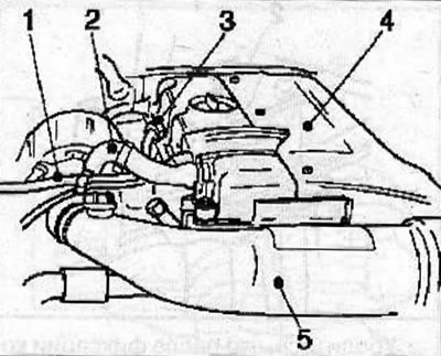
Disconnect the cooling system hose (1) from the cylinder head and expansion tank.
Disconnect the crankcase ventilation hose from the cylinder head cover.
Disconnect the fuel system ventilation hose from the air intake tube connecting the air filter and turbocharger.
Disconnect the connector from the air flow meter.
Disconnect the air intake pipe from the air filter, the turbocharger air intake (5), the crankcase ventilation hose (2) from the cylinder head cover.
Release the glow plug wires (3) from the clamps on the cylinder head cover.
Remove the wire harness support bracket from the cylinder head cover and intake manifold, then move it away from the cylinder head cover.
Remove the cylinder head cover from the cylinder head.
Remove the lower engine compartment protection.
Remove the vacuum pump (see the relevant chapter).
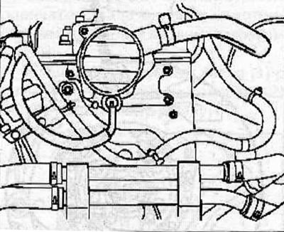
Mark the direction of rotation of the V-belt.
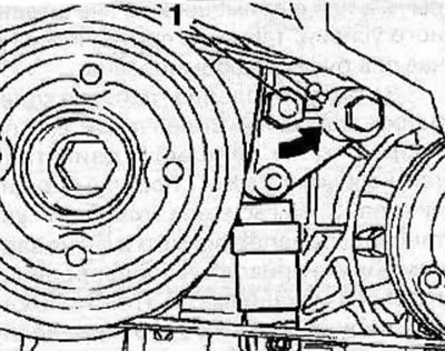
Turn the V-belt tensioner counterclockwise using the hexagonal boss (1), which will loosen the tension on the accessory drive V-belt and remove the belt from the engine pulleys.
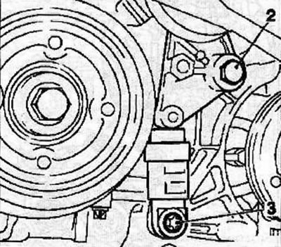
Remove the bolts (2 and 3) and remove the auxiliary drive V-belt tensioner.
Unscrew the bolts securing the protective cover (1) of the timing drive and remove the cover by carefully prying it off with a wide flat spatula (2).
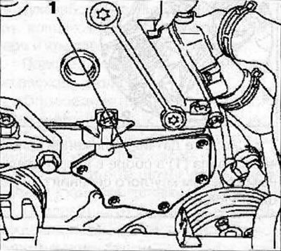
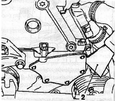
The timing belt cover must not be removed using a lever or with significant force, otherwise it will become deformed.
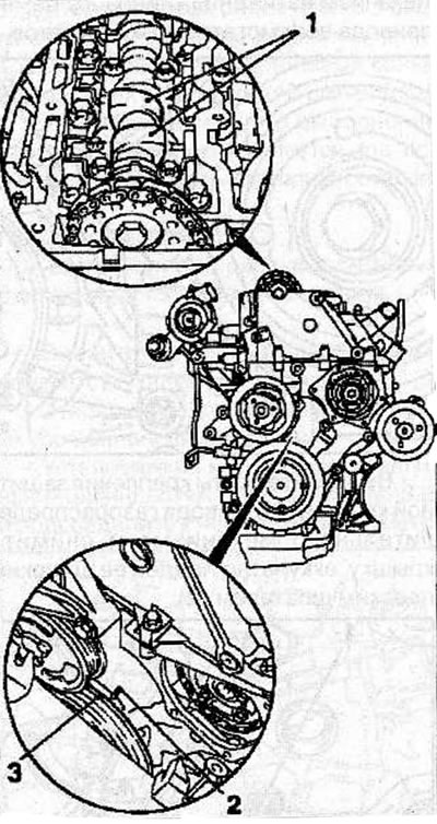
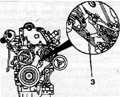
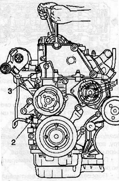
Using the vibration damper mounting bolt, turn the crankshaft in the direction of engine rotation so that the TDC mark of the 1st cylinder piston (3) on the vibration damper is positioned opposite the mark (2) on the rear casing of the timing drive. In this position of the piston, the camshaft cams (1) will be directed upwards.
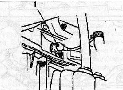
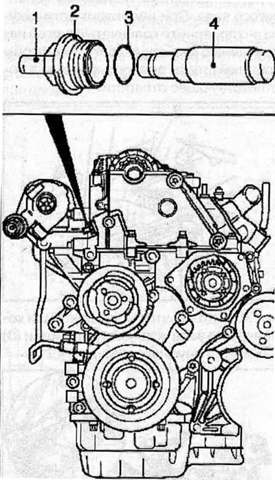
Remove the crankshaft position sensor (1) complete with O-ring from the cylinder block.
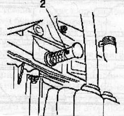
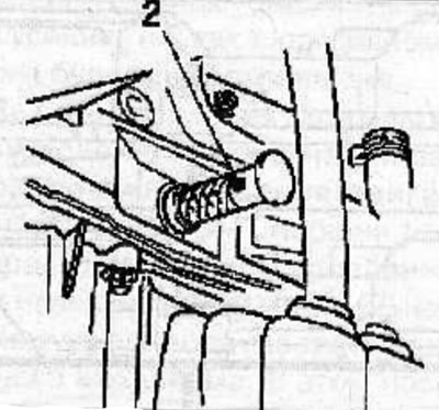
To fix the crankshaft, insert the KM-929 thrust pin (2) into the hole for the crankshaft position sensor. If necessary, carefully turn the crankshaft in the direction of engine rotation until the thrust pin is fully seated in the corresponding hole.
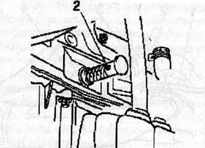
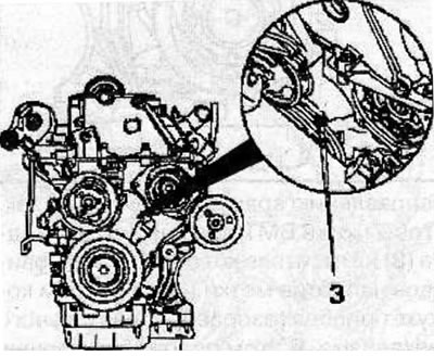
Make sure that after fixing the crankshaft, the timing marks (3) are opposite each other.
Make sure that the arrow (1) on the sprocket of the single-row high-pressure fuel pump (HPFP) drive chain matches the slot on the HPFP flange and the corresponding hole (2) in the fuel pump.
Fix the fuel injection pump in this position by inserting the KM-927 stop pin (3) into the fuel injection pump hole.
Material copied from this website [www.opelbook.ru]
Warning! If the stop pin does not enter the hole, repeat the installation of the piston of the 1st cylinder at TDC.
Install the measuring tool KM-932 (3) on the cylinder head. The pin (2) must be located in the hole (1) of the camshaft. If necessary, carefully turn the camshaft by the hexagon.
If the pin does not align with the hole, repeat the installation of the piston of the 1st cylinder at TDC.
Remove all tools used to check the valve timing.
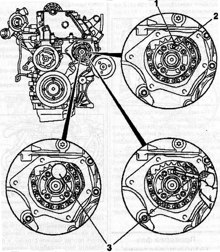
Checking the valve timing: 1 - arrow on the sprocket of the single-row high-pressure fuel pump drive chain; 2 - hole in the fuel pump; 3 - thrust pin KM-927.
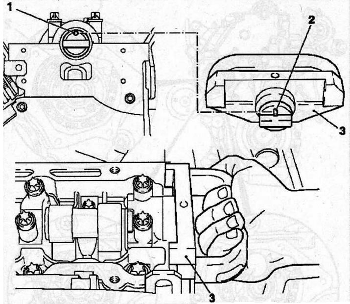
Installing the measuring tool KM-932 (3) on the cylinder head, while the pin (2) should be located in the hole (1) of the camshaft.
Clean the sealing surfaces of the protective cover and the timing case, wipe them with a clean, lint-free cloth.
Warning! After applying the sealant to the protective cover, it should be installed in place no later than 10 minutes later.
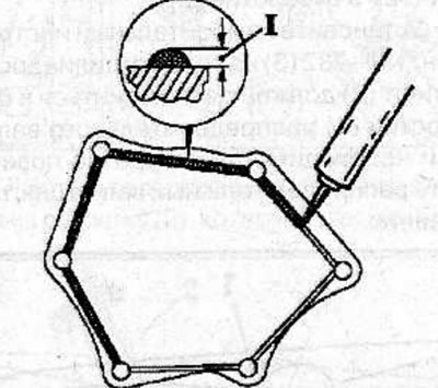
Apply approximately 2 mm of sealant (I) to the protective cover, install the cover and secure with the bolts, tightening them to a torque of 6 Nm.
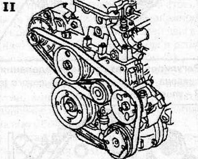
Install the accessory drive V-belt tensioner and secure with bolts, tightening them to a torque of 42 N·m.
Install the vibration damper and secure with bolts, tightening them to a torque of 23 Nm.
Place the V-belt according to the marks made during removal.
Install the crankshaft position sensor with a new sealing ring and tighten to 8 N·m.
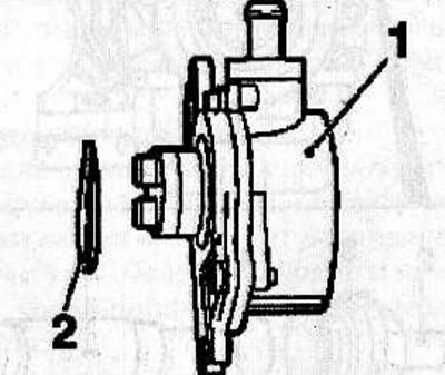
Install the vacuum pump (1) with a new sealing ring (2) (see the relevant chapter).
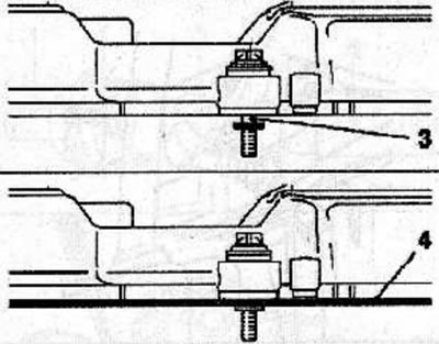
Install a new sealing gasket (4) into the special groove (3) located between the cylinder head cover and the bushing.
Apply sealant to the cylinder head cover (arrows), install the cover with a new gasket on the cylinder head and secure with bolts, tightening them to a torque of 8 Nm.
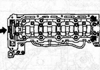
Install the wiring harness support bracket to the cylinder head cover and intake manifold.
Use clamps to secure the glow plug wires to the cylinder head cover.
Install and connect the air intake tube to the air cleaner, turbocharger air intake and cylinder head cover.
Connect the connector to the air flow meter.
Connect the fuel system breather hose to the air intake tube that connects the air filter to the turbocharger.
Connect the crankcase ventilation hose to the cylinder head cover.
Connect the coolant hose to the cylinder head and expansion tank.
Install the engine cover.
Install the lower engine compartment protection.
Adjusting the valve timing
Situation #1: The pin for setting the valve timing of the fuel pump does not fit into the hole in the flange of the fuel pump.
To fix the crankshaft, insert the KM-929 thrust pin (2) into the hole for the crankshaft position sensor. If necessary, carefully turn the crankshaft in the direction of engine rotation until the thrust pin is fully seated in the corresponding hole.
Remove the single-row chain tensioner (3) and the double-row chain tensioner (2). Remove the camshaft sprocket mounting bolt, holding the shaft by the hexagon with a wrench to prevent it from turning.
Install the new camshaft sprocket bolt and tighten it by hand. Check that the sprocket is positioned correctly on the camshaft.
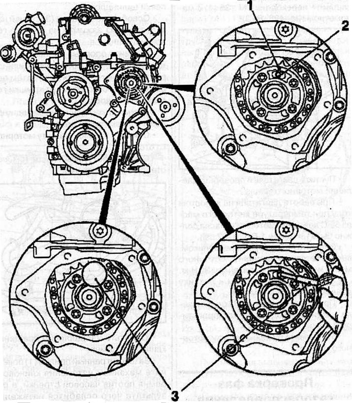
Adjusting the valve timing: 1 - arrow on the sprocket of the single-row high-pressure fuel pump drive chain; 2 - hole in the fuel pump; 3 - thrust pin KM-927.
Remove the bolts (1) securing the fuel injection pump sprocket.
Turn the fuel injection pump sprocket so that the arrow (1) on the sprocket aligns with the slot on the fuel injection pump flange and the hole (2) in the fuel pump.
Fix the fuel injection pump in this position by inserting the KM-927 stop pin (3) into the fuel injection pump hole.
Install the double-row chain tensioner (5) into place, with the closed side of the chain tensioner facing the tensioner guide. Screw on the cover (3) with a new sealing ring (4) and tighten it to a torque of 60 Nm.
Depending on the model, the tensioner may have a detachable pin (2). Install the pin (2) by pressing it in with a hammer handle. The finger will be in place when you hear a characteristic click.
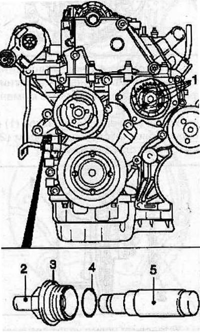
Double Row Chain Tensioner; 2 - finger; 3 - lid; 4 - sealing ring; 5 - double-row chain tensioner.
Remove the KM-927 thrust pin. Tighten the bolts (1) securing the fuel injection pump sprocket to a torque of 20 N·m.
Reinstall the KM-927 thrust pin into the hole (2).
Install the measuring tool KM-932 (3) on the cylinder head. The pin (2) must be located in the hole (1) of the camshaft. If necessary, carefully turn the camshaft by the hexagon.
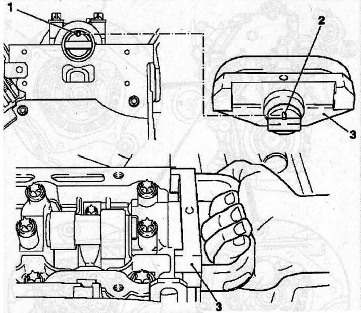
Installing the measuring tool KM-932 (3) on the cylinder head, while the pin (2) should be located in the hole (1) of the camshaft.
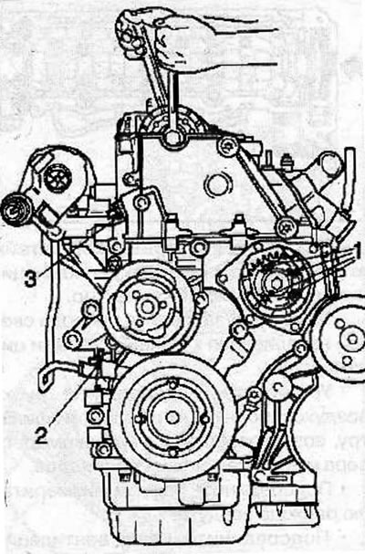
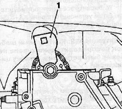
Install the thrust shoe (1) of the adjusting device (4) KM-933 into the hole of the camshaft sprocket. Secure the KM-933 tool to the cylinder head.
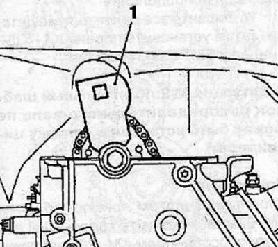
Insert the handle (2) into the hole in the stop shoe and gently push it in the direction of the arrow (in the direction opposite to the direction of rotation of the engine parts) and fix the shoe in this position with the clamping bolt (3).
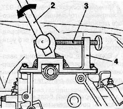
Make sure that the KM-927 thrust pin moves freely in the hole, otherwise, relieve the pressure on the thrust shoe by loosening the bolt (3).
Install the camshaft sprocket and secure with the bolt, tightening it as follows:
- 1st pass: 90 Nm;
- 2nd pass: turn to an angle of 60°;
- 3rd pass: turn to an angle of 30°.
Install the single-row chain tensioner (4) into the cylinder head with the closed side of the chain tensioner facing the tensioner guide. Screw on the cover (2) with a new sealing ring (3) and tighten it to a torque of 60 Nm.
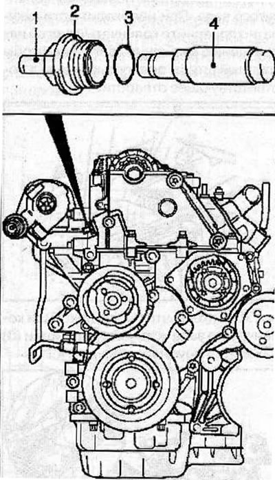
Warning! After installing a new single-row chain tensioner, disengage the tensioning mechanism by separating the pin (1). The pin will snap into place when you hear a distinctive click.
Remove all special adjustment devices.
Using the vibration damper mounting bolt, turn the crankshaft in the direction of engine rotation so that the TDC mark of the 1st cylinder piston (3) on the vibration damper is positioned opposite the mark (2) on the rear casing of the timing drive. In this position of the piston, the camshaft cams (1) will be directed upwards.
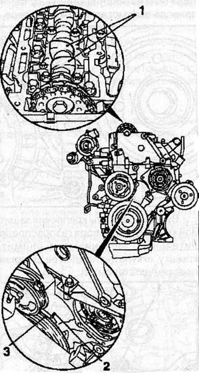
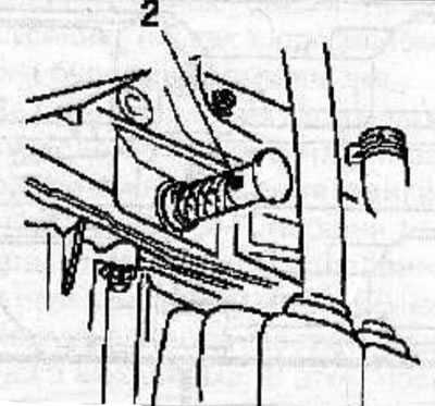
To fix the crankshaft, insert the KM-929 thrust pin into the hole for the crankshaft position sensor. If necessary, carefully turn the crankshaft in the direction of engine rotation until the thrust pin is fully seated in the corresponding hole.
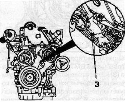
Make sure that after fixing the crankshaft, the timing marks (3) are opposite each other.
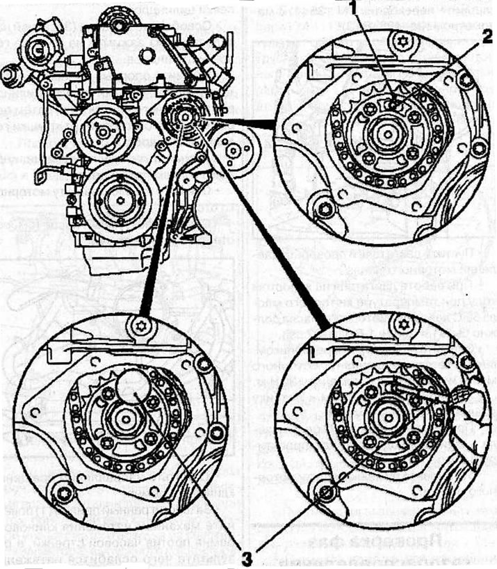
Setting the valve timing: 1 - arrow on the sprocket of the single-row high-pressure fuel pump drive chain; 2 - hole in the fuel pump: 3 - thrust pin KM-927.
Make sure that the arrow (1) on the sprocket of the single-row high-pressure fuel pump (HPFP) drive chain matches the slot on the HPFP flange and the corresponding hole (2) in the fuel pump.
Insert the thrust pin KM-927 (3) into the fuel injection pump hole.
Install the measuring tool KM-932 (3) on the cylinder head. The pin (2) must be located in the hole (1) of the camshaft.
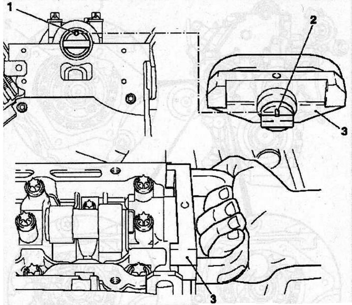
Installing the measuring tool KM-932 (3) on the cylinder head, while the pin (2) should be located in the hole (1) of the camshaft.
Remove all tools used to check the valve timing.
Install all previously removed parts, then set the piston of the 1st cylinder to TDC in the compression stroke.
Situation #2: The camshaft reference template cannot be inserted into the cylinder head.
Note: Use the KM-929 tool to lock the crankshaft and use the KM-927 tool to lock the high-pressure fuel pump in the TDC position of the 1st cylinder piston in the compression stroke.
Remove the KM-927 device that blocks the high-pressure fuel pump.
Remove the single-row chain tensioner (1), marking its installation position.
Remove the camshaft sprocket mounting bolt, holding the shaft by the hexagon with a wrench to prevent it from turning.
Install the new camshaft sprocket bolt and tighten it by hand. Check that the sprocket is positioned correctly on the camshaft.
Make sure that the arrow (1) on the fuel injection pump sprocket aligns with the slot on the fuel injection pump flange and the hole (2) in the fuel pump.
Fix the fuel injection pump in this position by inserting the KM-927 stop pin (3) into the fuel injection pump hole.
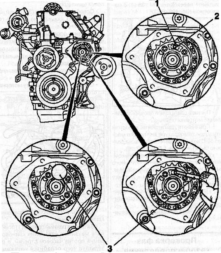
Setting the valve timing: 1 - arrow on the sprocket of the single-row high-pressure fuel pump drive chain; 2 - hole in the fuel pump; 3 - thrust pin KM-927.
Install the measuring tool KM-932 (3) on the cylinder head. The pin (2) must be located in the hole (1) of the camshaft. If necessary, carefully turn the camshaft by the hexagon.
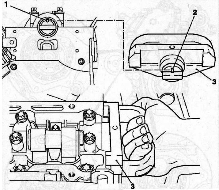
Installing the measuring tool KM-932 (3) on the cylinder head, while the pin (2) should be located in the hole (1) of the camshaft.
Install the thrust shoe (1) of the adjusting device (4) KM-933 into the hole of the camshaft sprocket. Secure the KM-933 tool to the cylinder head.
Insert the handle (2) into the hole in the stop shoe and gently push it in the direction of the arrow (in the direction opposite to the direction of rotation of the engine parts) and fix the shoe in this position with the clamping bolt (3).
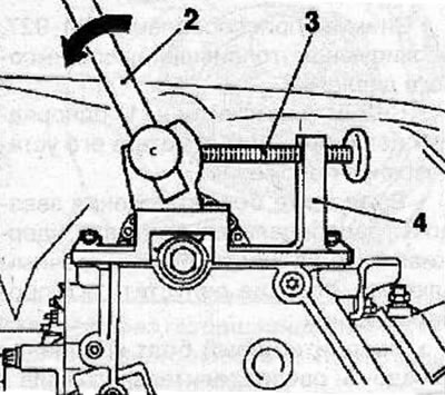
Make sure that the KM-927 thrust pin moves freely in the hole, otherwise, relieve the pressure on the thrust shoe by loosening the bolt (3).
Install the camshaft sprocket and secure with the bolt, tightening it as follows:
- 1st pass: 90 Nm;
- 2nd pass: turn to an angle of 60°;
- 3rd pass: turn to an angle of 30°.
Install the single-row chain tensioner (4) into the cylinder head with the closed side of the chain tensioner facing the tensioner guide. Screw on the cover (2) with a new sealing ring (3) and tighten it to a torque of 60 Nm.
Warning. After installing the new single-row chain tensioner, disengage the tensioning mechanism by disengaging the pin (1). The pin will be in place when a characteristic click is heard.
Remove all special adjustment devices.
Using the vibration damper mounting bolt, turn the crankshaft in the direction of engine rotation so that the TDC mark of the 1st cylinder piston (3) on the vibration damper is positioned opposite the mark (2) on the rear casing of the timing drive. In this position of the piston, the camshaft cams (1) will be directed upwards.
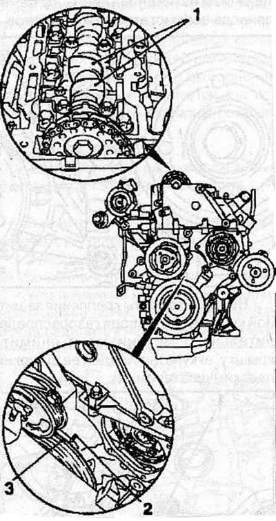
To prevent the crankshaft from turning, insert the KM-929 stop pin into the hole for the crankshaft position sensor. If necessary, carefully turn the crankshaft in the direction of engine rotation until the thrust pin is fully seated in the corresponding hole.
Make sure that after fixing the crankshaft, the timing marks (3) are opposite each other.

Setting the valve timing: 1 - arrow on the sprocket of the single-row high-pressure fuel pump drive chain; 2 - hole in the fuel pump; 3 - thrust pin KM-927.
Make sure that the arrow (1) on the sprocket of the single-row high-pressure fuel pump (HPFP) drive chain matches the slot on the HPFP flange and the corresponding hole (2) in the fuel pump.
Fix the fuel injection pump in this position by inserting the KM-927 stop pin (3) into the fuel injection pump hole.
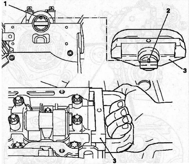
Installing the measuring tool KM-932 (3) on the cylinder head, while the pin (2) should be located in the hole (1) of the camshaft.
Install the measuring tool KM-932 (3) on the cylinder head. The pin (2) must be located in the hole (1) of the camshaft.
Remove all tools used to check the valve timing.
Install all previously removed parts, then set the piston of the 1st cylinder to TDC in the compression stroke.
Visitor comments