


Contents: Removal ⬇ Installation ⬇
Removal
Set the piston of the 1st cylinder to TDC in the compression stroke (see the relevant chapter).
Mark the installation position and remove the single-row chain tensioner (3).
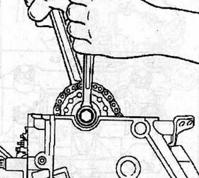
Heat the bolts (1) securing the single-row chain guide with a hair dryer and unscrew them.
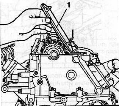
Mark the installation position and remove the single-row chain guide by lifting it upwards.
Mark the installation position and remove the double-row chain tensioner (2).
Remove the measuring tool KM-932 from the cylinder head and remove the thrust pin KM-927 from the fuel injection pump pulley hole.
Remove the camshaft sprocket mounting bolt, holding the shaft by the hexagon with a wrench to prevent it from turning.
Remove the camshaft sprocket from the single row chain.
Note: To facilitate assembly, tie a single-strand chain to the appropriate point on the cylinder head.
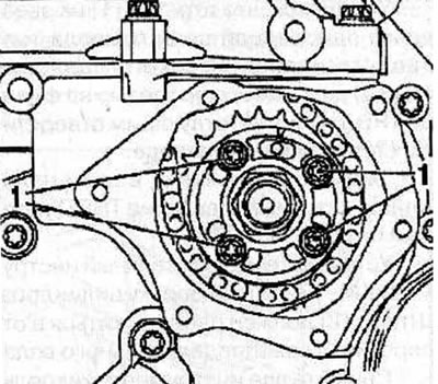
Unscrew the bolts (1) and remove the fuel injection pump sprocket.
Remove the single row chain from the top of the cylinder head.
Installation
Place a single row chain on the camshaft sprocket and secure the sprocket to the camshaft by screwing in and hand tightening a new bolt.
Install the camshaft sprocket into the single row chain, then install the sprocket onto the camshaft.
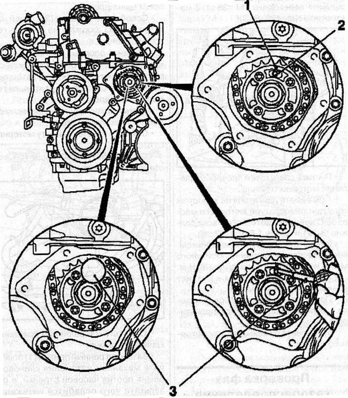
Warning! The arrow (1) on the fuel injection pump sprocket must align with the recess on the fuel pump flange and the hole (2) in the fuel pump.
Setting the valve timing: 1 - arrow on the sprocket of the single-row high-pressure fuel pump drive chain; 2 - hole in the fuel pump; 3 - thrust pin KM-927.
Secure the fuel injection pump by inserting the thrust pin (3) KM-927 into the hole in the flange.
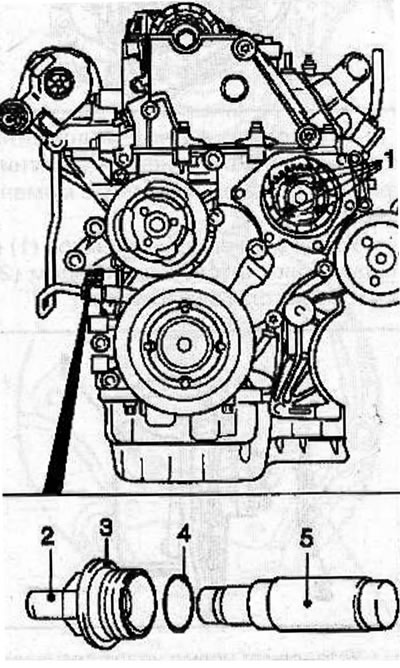
Install the double-row chain tensioner (5) into place, with the closed side of the chain tensioner facing the tensioner guide. Screw on the cover (3) with a new sealing ring (4) and tighten it to a torque of 60 Nm.
Depending on the model, the tensioner may have a detachable pin (2). Install the pin (2) by pressing it in with a hammer handle. The finger will be in place when you hear a characteristic click.
Remove the KM-927 thrust pin from the high-pressure fuel pump.
Tighten the bolts (1) securing the fuel injection pump sprocket to a torque of 20 Nm.
Fix the THVD by inserting the KM-927 thrust pin into the hole in the flange.
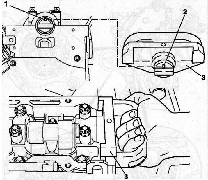
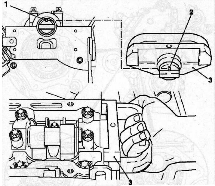
Install the measuring tool KM-932 (3) on the cylinder head. The pin (2) must be located in the hole (1) of the camshaft.
Installing the measuring tool KM-932 (3) on the cylinder head, while the pin (2) should be located in the hole (1) of the camshaft.
Tighten the new camshaft sprocket retaining bolt.
Install the guide (1) of the single-row chain in accordance with the previously applied marks.
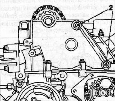
Using new bolts (2), secure the single-row chain guide and tighten the bolts to 8 Nm.
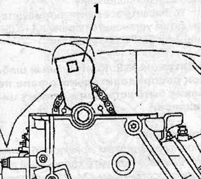
Install the thrust shoe (1) of the adjusting device (4) KM-933 into the hole of the camshaft sprocket. Secure the KM-933 tool to the cylinder head.
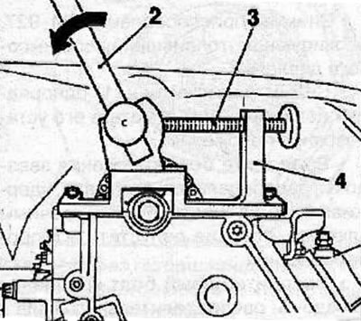
Insert the handle (2) into the hole in the stop shoe and gently push it in the direction of the arrow (in the direction opposite to the direction of rotation of the engine parts) and fix the shoe in this position with the clamping bolt (3).
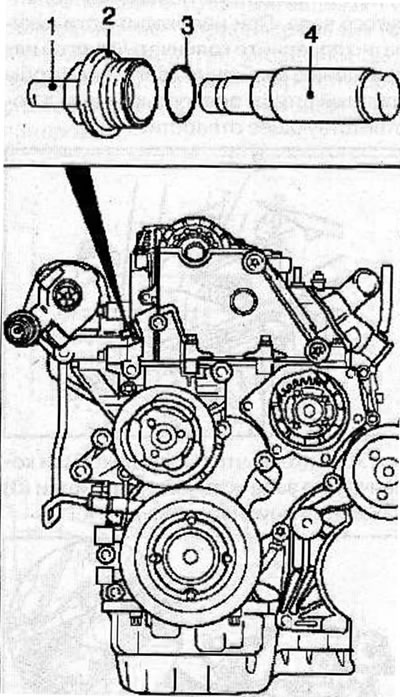
Make sure that the KM-927 thrust pin moves freely in the hole, otherwise, relieve the pressure on the thrust shoe by loosening the bolt.
Tighten the new camshaft sprocket bolt as follows:
- 1st pass: 90 Nm;
- 2nd pass: turn to an angle of 60°;
- 3rd pass: turn to an angle of 30°.
Install the single-row chain tensioner (4) into the cylinder head with the closed side of the chain tensioner facing the tensioner guide. Screw on the cover (2) with a new sealing ring (3) and tighten it to a torque of 60 Nm.
Remove all special adjustment devices.
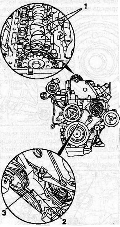
Using the vibration damper mounting bolt, turn the crankshaft in the direction of engine rotation so that the TDC mark of the 1st cylinder piston (3) on the vibration damper is positioned opposite the mark (2) on the rear casing of the timing drive.
Make sure that in this position of the piston of the 1st cylinder, the camshaft cams (1) are directed upwards.
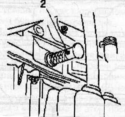
To fix the crankshaft, insert the KM-929 thrust pin (2) into the hole for the crankshaft position sensor. If necessary, carefully turn the crankshaft in the direction of engine rotation so that the thrust pin is fully inserted into the corresponding hole.
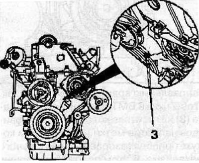
Make sure that after fixing the crankshaft, the timing marks (3) are opposite each other.
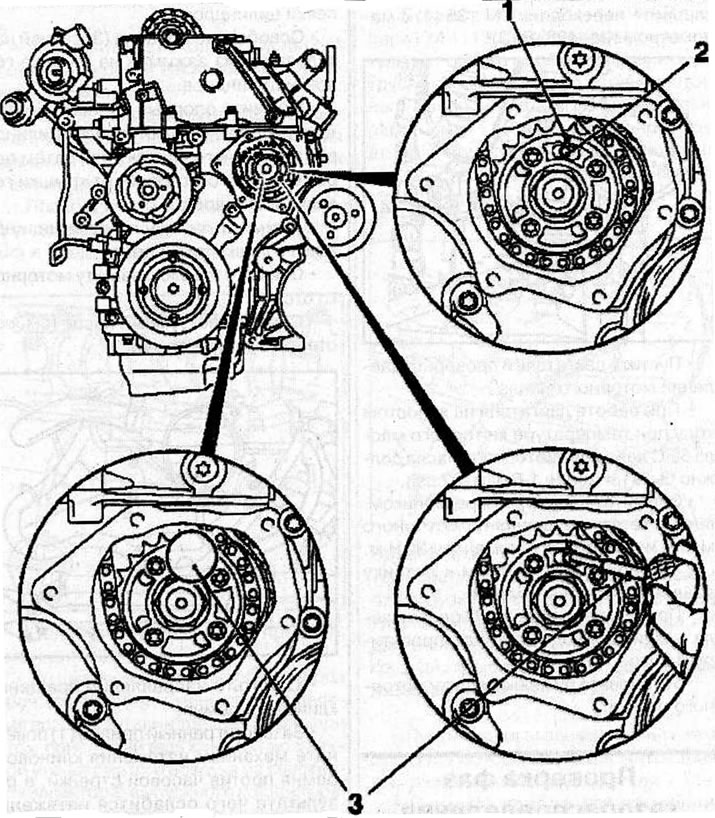
Make sure that the arrow (1) on the single-row high-pressure fuel pump (HPFP) drive chain sprocket aligns with the slot on the fuel pump flange and the corresponding hole (2) in the fuel pump.
Setting the valve timing: 1 - arrow on the sprocket of the single-row high-pressure fuel pump drive chain; 2 - hole in the fuel pump; 3 - thrust pin KM-927.
Fix the fuel injection pump in this position by inserting the KM-927 stop pin (3) into the fuel injection pump hole.
Install the KM-932 measuring tool (3) on the cylinder head, with the pin (2) positioned in the hole (1) of the camshaft.
Installing the measuring tool KM-932 (3) on the cylinder head, while the pin (2) should be located in the hole (1) of the camshaft.
Install all previously removed parts, then set the piston of the 1st cylinder to TDC in the compression stroke.
(Text copied from an online resource: «OPELBOOK.ru»)
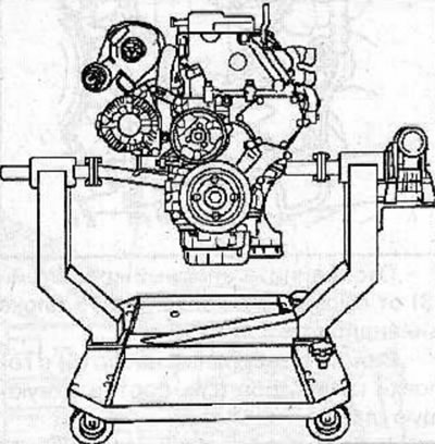
Install the engine on the KM 412 stand with KM-412-16 and KM-412-8-1 adapters.
Remove the accessory drive belt (see the relevant chapter).
Remove the generator (see the relevant chapter).
Disconnect the turbocharger feed (2) and return (4) oil lines from the cylinder block.
Visitor comments