


Contents: Removal ⬇ Installation ⬇
Warning! Removal of the timing drive housing is necessary when performing the following operations:
- removing and installing the sprocket (1) of the fuel injection pump drive;
- removal and installation of the double-row timing chain (2):
- removal and installation of the guide (3) of the double-row timing chain;
- removing and installing the drive sprocket (4) of the timing mechanism from the crankshaft;
- removing and installing the tensioner shoe (5) of the timing chain;
- replacing the gasket of the housing (6) of the timing drive;
- removing and installing the oil pump.
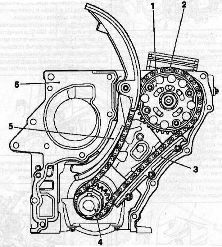
Gas distribution mechanism drive housing: 1 - fuel injection pump drive sprocket; 2 - double-row timing chain; 3-guide of the two-row chain of the gas distribution mechanism drive: 4-leading sprocket of the gas distribution mechanism drive; 5 - chain tensioner shoe; 6 - timing gear housing gasket
Removal
Remove the engine (see the relevant chapter).
Disconnect the wiring harness from the generator, oil pressure sensor and ground wire.
Remove both cylinder block mounting brackets.
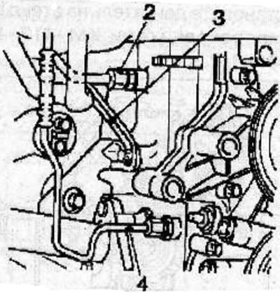
Disconnect the support bracket (3) from the exhaust manifold and cylinder block.
Remove the vacuum pump (5) from the cylinder head (see the relevant chapter).
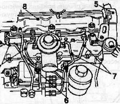
Mark the installation position and remove the clamps (6) securing the high-pressure fuel pipes.
Disconnect the high-pressure fuel pipes (7) from the fuel injectors and the high-pressure fuel pump.
Remove the cylinder head cover (8).
Loosen the tightening of the vibration damper mounting bolt (2), holding the crankshaft from turning with the device (3) KM-977-1 and KM-956. There is no need to completely unscrew the vibration damper bolt.
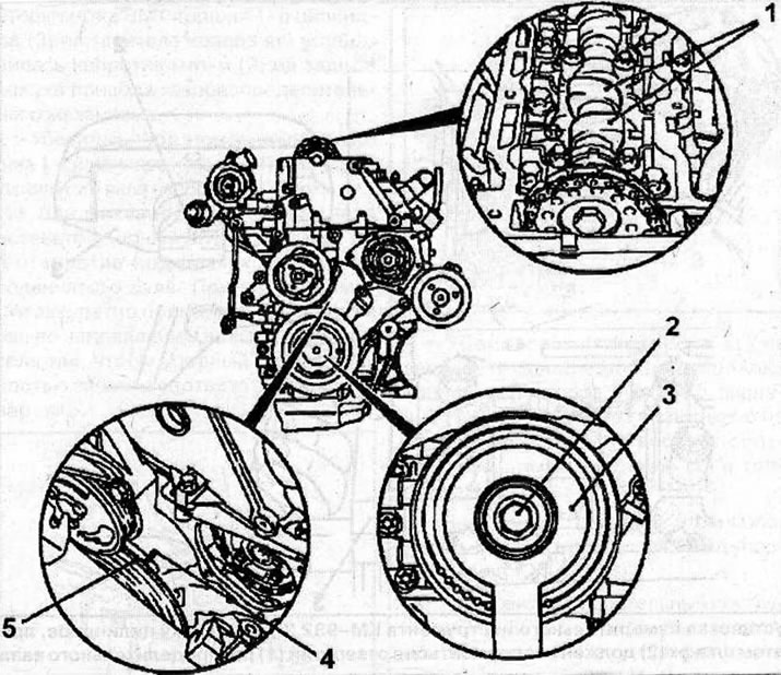
Using the vibration damper mounting bolt, turn the crankshaft in the direction of engine rotation so that the mark (5) "TDC cylinder No. 1" is positioned at some distance from the mark (4) on the timing cover. In this position, the cams (1) of the valve drive of the 1st cylinder should be directed upwards.
Remove the crankshaft position sensor (1) together with the sealing ring from the cylinder block.
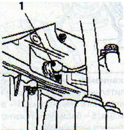
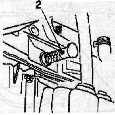
To fix the crankshaft, insert the KM-929 thrust pin (2) into the hole for the crankshaft position sensor. If necessary, carefully turn the crankshaft in the direction of engine rotation until the thrust pin is fully seated in the corresponding hole.
Make sure that after fixing the crankshaft, the timing marks (3) are opposite each other.
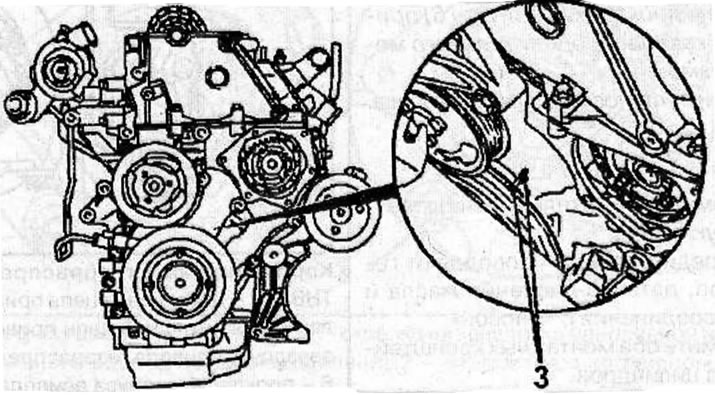
Remove the vibration damper.
Remove the water pump pulley (5).
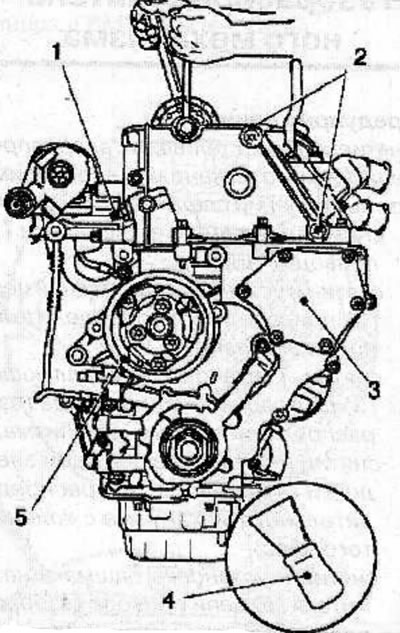
Unscrew the bolts securing the protective cover (3) of the timing drive and remove the cover by carefully prying it off with a wide flat spatula (4).
Heat the bolts (2) for fastening the single-row chain guide with a hair dryer and unscrew them.
Mark the installation position and remove the single-row chain guide by lifting it upwards.
Mark the installation position and remove the double-row chain tensioner (1).
Remove the camshaft sprocket mounting bolt, holding the shaft by the hexagon with a wrench to prevent it from turning.
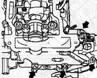
Remove the bolts (arrows), while marking their location, as the bolts are of different lengths.
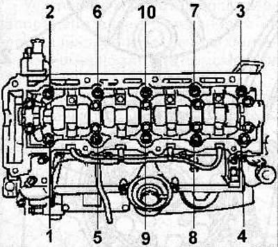
Loosen the cylinder head bolts in the sequence shown in the figure, first by a quarter, then by half a turn, and unscrew them.
Remove the cylinder head.
Remove the oil pan from the cylinder block.
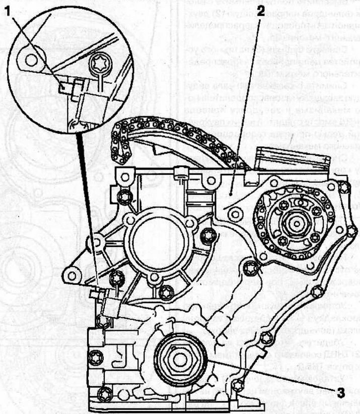
Remove the double-row chain tensioner (1).
Unscrew the bolts securing the casing (2) of the timing drive.
Remove the seal (3) from the timing drive housing, being careful not to damage the sealing surfaces.
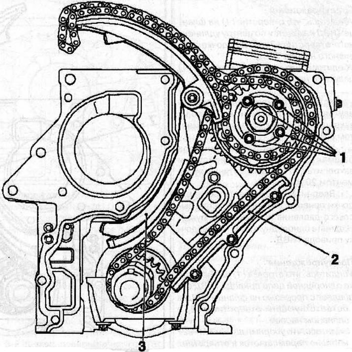
Unscrew the bolts (1) and remove the fuel injection pump sprocket together with the chain.
Unscrew the bolts and remove the guide (2) of the double-row timing chain from the cylinder block.
Remove the shoe (3) of the timing chain tensioner.
Remove the timing drive sprocket and the fuel injection pump drive sprocket from the crankshaft together with the double-row timing drive chain attached to them.
Remove the timing case sealing gasket.
Installation
Clean the mating surfaces and remove any remaining old gasket material.
Check the condition of all parts for wear and mechanical damage and replace them if necessary.
Install a new sealing gasket (1) onto the front side of the cylinder block.
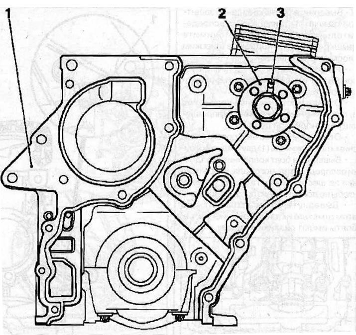
Make sure that the recess on the flange (2) of the high-pressure fuel pump matches the hole (3) on the high-pressure fuel pump body.
Install the sprocket (6) with the double-row chain (5) placed on it onto the crankshaft, and the sprocket (3) onto the injection pump shaft.
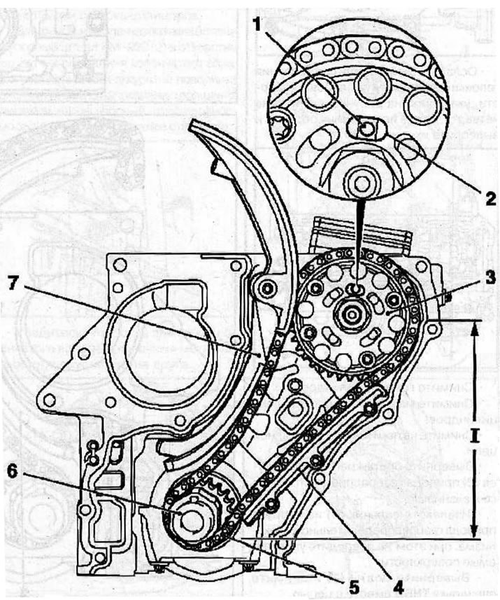
Warnings:
- Make sure that the hole (1) on the fuel injection pump flange is centered in the elongated hole (2) on the fuel injection pump sprocket.
- Make sure the tension side (1) of the chain is tight.
Install the guide (4) of the double-row chain onto the cylinder block and secure with bolts, tightening them to a torque of 8 Nm.
Install the tensioner shoe (7) onto the cylinder block and secure it with bolts, tightening them to a torque of 20 Nm.
Install the high pressure fuel pump drive sprocket mounting bolts and tighten them by hand. Place the single-row chain on the fuel injection pump drive sprocket.
Warnings:
- Make sure that the arrow (1) on the single-row fuel injection pump drive chain sprocket matches the slot on the fuel injection pump flange and the corresponding hole (2) in the fuel pump.
- Make sure that the KM-927 thrust pin moves freely in the hole.
Install the timing drive housing onto the cylinder block and secure with bolts, tightening them evenly to a torque of 20 Nm.
Lubricate the working edges of the new oil seal with clean engine oil and install it on the protective sleeve KM-935-1 (1), then attach the sleeve to the crankcase.
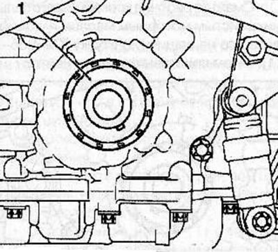
Install the protective sleeve KM-935-2 (2) on the oil seal, then use the vibration damper mounting bolt to press the oil seal into the crankcase seat.
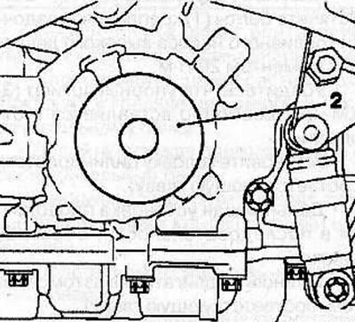
Warning! Remove the stop pin (1) KM-929, which was used to lock the crankshaft, and the pin KM-927, which was used to lock the high-pressure fuel pump.
Install the vibration damper on the crankshaft, use the KM-977-1 (2) and KM-956-1 tools to prevent the vibration damper from turning and secure it with a new bolt, tightening it as follows:
- 1st pass: 150 Nm;
- 2nd pass: turn to an angle of 45°;
- 3rd pass: turn further at an angle of 15°.
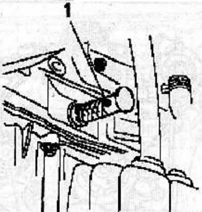
Lock the fuel injection pump by inserting the stop pin (1) KM-927 into the hole for the crankshaft angle sensor.
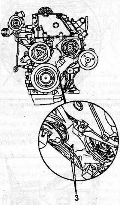
Make sure that after fixing the crankshaft, the timing marks (3) are opposite each other.
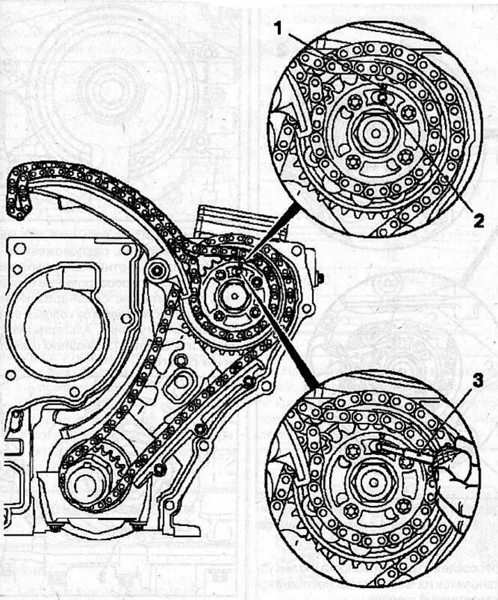
Make sure that the arrow (1) on the sprocket of the single-row drive chain of the high-pressure fuel pump (HPFP) coincides with the slot on the flange of the HPFP and the corresponding hole (2) in the fuel pump (see picture on next page).
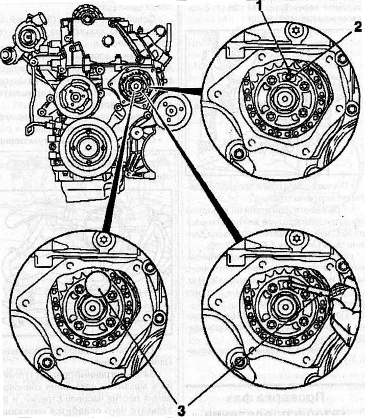
Setting the valve timing: 1 - arrow on the sprocket of the single-row high-pressure fuel pump drive chain; 2 - hole in the fuel pump; 3 - thrust pin KM-927.
Fix the high-pressure fuel pump in this position by inserting the KM-927 thrust pin (3) into the fuel injection pump hole.
Warning! If the stop pin does not enter the hole, repeat the installation of the piston of the 1st cylinder at TDC.
Install the double-row chain tensioner (5) into place, with the closed side of the chain tensioner facing the tensioner guide. Screw on the cover (3) with a new sealing ring (4) and tighten it to a torque of 60 Nm.
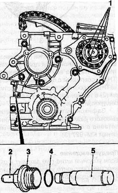
Depending on the model, the tensioner may have a detachable pin (2). Install the pin (2) by pressing it in with a hammer handle. The finger will be in place when you hear a characteristic click.
[Original source on the website: opelbook.ru]
Remove the KM-927 thrust pin. Tighten the bolts (1) securing the high-pressure fuel pump sprocket to a torque of 20 N·m.
Make sure that the stop pin (3) KM-927 can be inserted freely into the hole.
Install the cylinder head (see the relevant chapter).
Further installation is carried out in the reverse order of removal.
Install the engine into the car (see the relevant chapter).
Visitor comments