
OpelBook.ru
Cars AvtoVAZ Cars Mitsubishi Cars BMW Cars Mercedes Cars Nissan Cars Toyota Cars Chevrolet
English Русский
Български
Беларускі
Український
Српски
Hrvatski
Română
Polski
Slovenský
Magyar
 |  Sitemap  |  Contacts  |    


Main Astra Corsa Insignia Kadett Omega Vectra Zafira Others Articles
Frontera A (1991-1998, petrol) Frontera B (1998-2004) Ascona C (1981-1988) Vivaro A (2001-2014)
  • Main
  • Opel
  • Frontera B
  • Power unit
  • Diesel engines 2.2 l
  • Camshafts

Camshafts (Opel Frontera B)

            0

Contents: Removal ⬇ Installation ⬇

Removal


Set the piston of the 1st cylinder to TDC in the compression stroke (see the relevant chapter).

Remove the vacuum pump (see the relevant chapter).

Mark the installation position and remove the single-row chain tensioner (1).
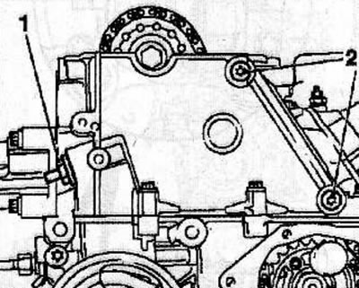
Mark the installation position and remove the single-row chain tensioner (1).


Heat the bolts (2) for fastening the single-row chain guide with a hair dryer and unscrew them.

Mark the installation position and remove the single-row chain guide by lifting it upwards.

Remove the measuring tool KM-932 from the cylinder head and remove the thrust pin KM-927 from the hole in the fuel injection pump pulley.

Remove the camshaft sprocket mounting bolt, holding the shaft by the hexagon with a wrench to prevent it from turning.
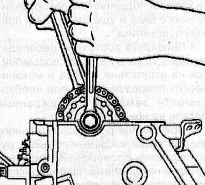
Remove the camshaft sprocket mounting bolt, holding the shaft by the hexagon with a wrench to…


Remove the camshaft sprocket from the single row chain. To facilitate assembly, secure the single-row chain to the timing case.


Warning: Before removing the camshaft bearing caps, mark their mounting position.


Loosen the camshaft bearing cap bolts by turning them half a turn or a full turn in a spiral motion in the sequence shown in the illustration. Then, in the same sequence, unscrew the bolts, remove the bearing caps, and then the camshaft.
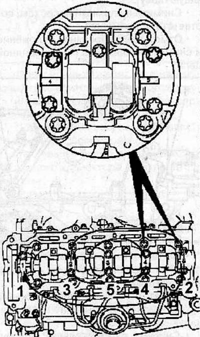
Loosen the camshaft bearing cap bolts by turning them half a turn or a full turn in a spiral motion…


Warning! If the camshaft is to be replaced, the valve rocker arms must also be replaced.


Installation


Clean the mating surfaces of the camshaft bearing cap and remove any remaining sealant.

Check the condition of the camshaft and bearing caps for wear and mechanical damage and, if necessary, replace damaged parts with new ones.

When replacing the camshaft, install new rocker arms, using the installation marks located on the ends adjacent to the fuel rail.

Apply a thin layer of sealant to the areas indicated by arrows in the figure.
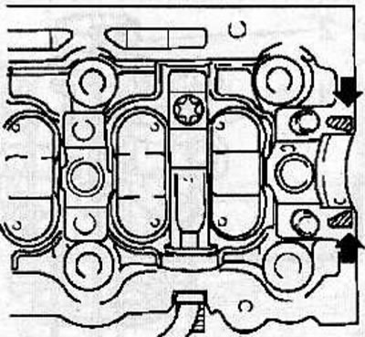
Apply a thin layer of sealant to the areas indicated by arrows in the figure.


[Article posted on an online resource: www.opelbook.ru]


Inspect the working surfaces of the camshaft and cam bearings for scratches and wear. If such damage is found, replace the camshaft. If the cylinder head running surfaces are excessively worn, replace the cylinder head.

Lubricate the contact surfaces of the tappets and camshaft with grease MoS2 and carefully install the camshafts back into place in the cylinder head.

Warning! When installing, the identification numbers on the camshaft bearing caps must match the numbers on the cylinder head.


Install the camshaft bearing caps and tighten their mounting bolts in a spiral pattern, following the sequence shown in the figure. First tighten all bolts by half a turn or a full turn, and then tighten them in the same sequence to a torque of 15 Nm.
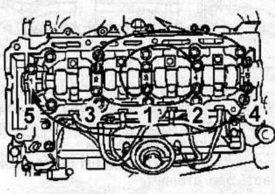
Install the camshaft bearing caps and tighten their mounting bolts in a spiral pattern, following…


Place a single row chain on the camshaft sprocket and secure the sprocket to the camshaft by screwing in and hand tightening a new bolt.

Warning! The sprocket must fit snugly on the shaft.


Install the guide (1) of the single-row chain in accordance with the previously applied marks.
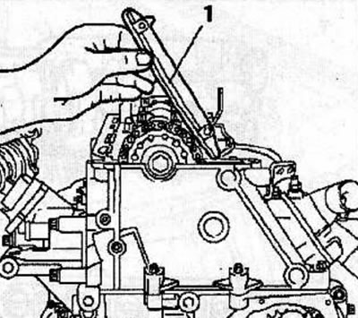
Install the guide (1) of the single-row chain in accordance with the previously applied marks.


Using new bolts (2), secure the single-row chain guide and tighten the bolts to 8 Nm.
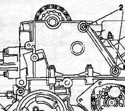


Using new bolts (2), secure the single-row chain guide and tighten the bolts to 8 Nm.


Make sure that the arrow (1) on the sprocket of the single-row high-pressure fuel pump (HPFP) drive chain matches the slot on the HPFP flange and the corresponding hole (2) in the fuel pump.
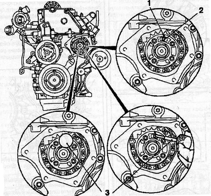
Setting the valve timing: 1 - arrow on the sprocket of the single-row high-pressure fuel pump drive…

Setting the valve timing: 1 - arrow on the sprocket of the single-row high-pressure fuel pump drive chain; 2 - hole in the fuel pump; 3 - thrust pin KM-927.


Fix the fuel injection pump in this position by inserting the KM-927 stop pin (3) into the fuel injection pump hole.

Install the thrust shoe (1) of the adjusting device (4) KM-933 into the hole of the camshaft sprocket. Secure the KM-933 tool to the cylinder head.
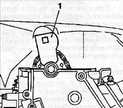
Install the thrust shoe (1) of the adjusting device (4) KM-933 into the hole of the camshaft…


Insert the handle (2) into the hole in the stop shoe and gently push it in the direction of the arrow (in the direction opposite to the direction of rotation of the engine parts) and fix the shoe in this position with the clamping bolt (3).
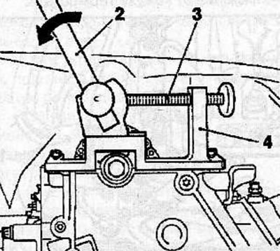


Insert the handle (2) into the hole in the stop shoe and gently push it in the direction of the…


Make sure that the KM-927 thrust pin moves freely in the hole, otherwise, relieve the pressure on the thrust shoe by loosening the bolt.

Tighten the new camshaft sprocket bolt as follows:;
  • 1st pass: 90 Nm;
  • 2nd pass; turn to an angle of 60°;
  • 3rd pass: turn to an angle of 30°.

Install the single-row chain tensioner (4) into the cylinder head with the closed side of the chain tensioner facing the tensioner guide. Screw on the cover (2) with a new sealing ring (3) and tighten it to a torque of 60 Nm.
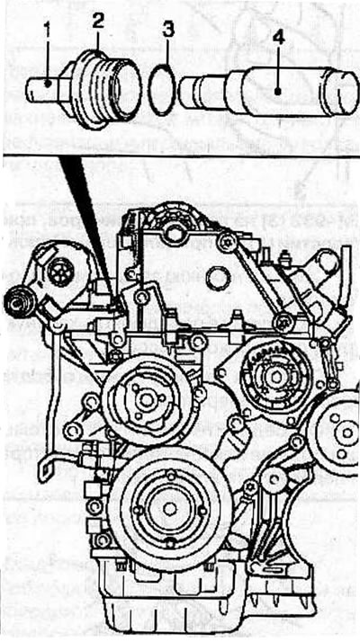
Install the single-row chain tensioner (4) into the cylinder head with the closed side of the chain…


Warning! After installing a new single-row chain tensioner, disengage the tensioning mechanism by separating the pin (1). The pin will snap into place when you hear a distinctive click.


Remove all special adjustment devices.


Using the vibration damper mounting bolt, turn the crankshaft in the direction of engine rotation so that the TDC mark of the 1st cylinder piston (3) on the vibration damper is positioned opposite the mark (2) on the rear casing of the timing drive.
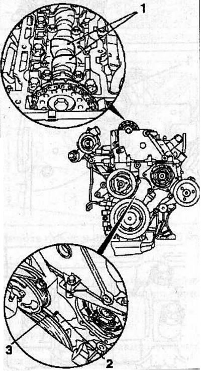
Using the vibration damper mounting bolt, turn the crankshaft in the direction of engine rotation…


Make sure that in this position of the piston of the 1st cylinder, the camshaft cams (1) are directed upwards.

To prevent the crankshaft from turning, insert the KM-929 stop pin (1) into the hole for the crankshaft position sensor. If necessary, carefully turn the crankshaft in the direction of engine rotation until the thrust pin is fully seated in the corresponding hole.
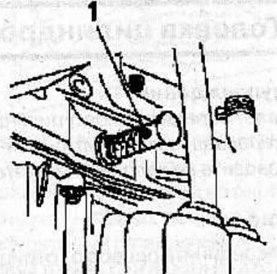
To prevent the crankshaft from turning, insert the KM-929 stop pin (1) into the hole for the…


Make sure that after fixing the crankshaft, the timing marks (3) are opposite each other.
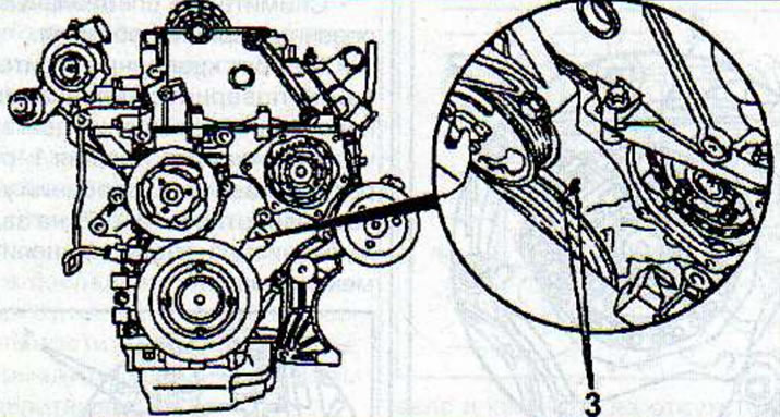


Make sure that after fixing the crankshaft, the timing marks (3) are opposite each other.


Install the measuring tool KM-932 (3) on the cylinder head. The pin (2) must be located in the hole (1) of the camshaft.
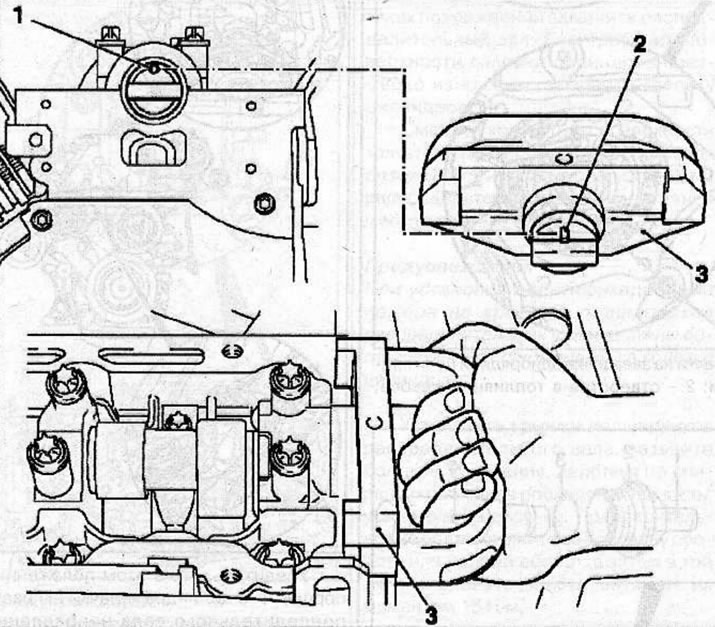
Installing the measuring tool KM-932 (3) on the cylinder head, while the pin (2) should be located…

Installing the measuring tool KM-932 (3) on the cylinder head, while the pin (2) should be located in the hole (1) of the camshaft.


Install all previously removed parts, then set the piston of the 1st cylinder to TDC in the compression stroke.


This article is available at russian, bulgarian, belarusian, ukrainian, serbian, croatian, romanian, polish, slovak, hungarian
Checking the article: Chernov Alexander

Share information:

Previous articles
Opel Frontera B: Diesel engines 2.2 l
Next articles

Vacuum pump
Exhaust manifold
Intake manifold
Cylinder head cover
Replacing the front crankshaft oil seal
Gas distribution mechanism drive housing
Cylinder head
Cylinder head repair
Flywheel — removal and installation
Replacing the rear crankshaft oil seal
Balance shaft block
Replacing connecting rod bearing shells


See similar ones from other Opel car manuals:
▶ Removal and installation of camshafts and valve lifters,… Opel Astra H (2004-2009)
▶ Removal and installation of gear wheels of crankshaft and… Opel Corsa B (1993-2000)
▶ Replacing camshafts Opel Insignia A (2008-2017)
▶ Camshafts and hydraulic tappets — removal, inspection and… Opel Omega B2 (1999-2003)
▶ Camshafts, repair dimensions for models C16NZ2, 1.8 and 2.0… Opel Vectra A (1988-1995, petrol)
Link to this page in different formats

Visitor comments


No comments yet


How much will 37 + 49 =


Vivaro A (2001-2014) 
  • General information
  • User manual
  • Power unit
  • Petrol engine F4R
  • Diesel engine F9Q
  • Diesel engine G9U
  • Transmission
  • Clutch and drive shafts
  • Manual gearbox
  • Chassis
  • Front suspension
  • Rear suspension
  • Brake system
  • Body
  • Exterior
  • Interior
  • Electrical equipment
  • Heating and ventilation
  • Air conditioner
  • Equipment and devices
  • Electrical diagrams
Ascona C (1981-1988) 
  • General information
  • Maintenance
  • Power unit
  • Gasoline engines
  • Diesel engines
  • Cooling system
  • Fuel and exhaust system
  • Contact ignition system
  • Contactless ignition system
  • Transmission
  • Clutch
  • Mechanical gearbox
  • Automatic gearbox
  • Drive shafts
  • Chassis
  • Steering
  • Brake system
  • Car suspension
  • Body
  • Exterior
  • Interior
  • Doors and windows
  • Electrical equipment
  • Equipment and devices
  • Power devices
  • Electrical circuits
Frontera B (1998-2004) 
  • General information
  • User manual
  • Maintenance
  • Power unit
  • Petrol engines 2.2 l
  • Petrol engines 3.2 l
  • Diesel engines 2.2 l
  • Cooling system
  • Fuel system (petrol)
  • Fuel system (diesel)
  • Ignition system
  • Transmission
  • Clutch
  • Manual gearbox MUA5C
  • Automatic gearbox 4L30E
  • Chassis
  • Suspension and axles
  • Steering
  • Brake system
  • Body
  • Exterior
  • Interior
  • Doors, locks and windows
  • Heating and air conditioning
  • Electrical equipment
  • Power devices
  • Equipment and devices
  • Lighting and signaling
  • Electrical diagrams
Frontera A (1991-1998, petrol) 
  • General information
  • Introduction to guide
  • User manual
  • Maintenance
  • Power unit
  • Engine repair
  • Lubrication system
  • Cooling system
  • Power and exhaust system
  • Engine electrics
  • Transmission
  • Clutch
  • Mechanical gearbox
  • Cardan shafts
  • Chassis
  • Brake system
  • Front suspension
  • Rear suspension
  • Steering
  • Body
  • Repair and care
  • Electrical equipment
  • Equipment and devices
  • Electrical circuits
OpelBook.ru © 2017–2026 · Mobile version · · Sitemap: EN BG BY UA RS HR RO PL SK HU · Feedback · Site search
Astra F, petrol · Astra G, petrol · Astra G · Astra H · Astra J, petrol · Corsa B · Corsa C, petrol · Corsa C · Insignia A · Kadett D · Kadett E · Omega A · Omega B · Omega B2 · Vectra A, petrol · Vectra A · Vectra B, petrol · Vectra B · Vectra C · Zafira A, petrol · Frontera A, petrol · Frontera B · Ascona C · Vivaro A ·
We want your visit to be comfortable 🤝! We use cookies 🍪 to make that happen.