


Contents: Removal ⬇ Installation ⬇
Removal
Remove the cylinder head (see the relevant chapter).
Warning! Place the removed cylinder head on wooden blocks to avoid damaging the injectors, glow plugs and valves.
Remove the exhaust manifold with turbocharger, generator bracket, lower part of the intake manifold and engine lifting eyes from the cylinder head.
Warning: Before removing the camshaft bearing caps, mark their mounting position.
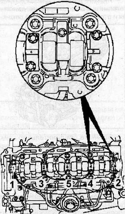
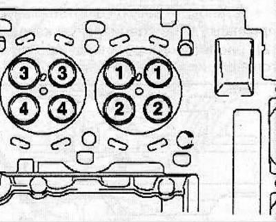
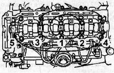
Loosen the camshaft bearing cap bolts by turning them half a turn or a full turn in a spiral motion in the sequence shown in the illustration. Then, in the same sequence, unscrew the bolts, remove the bearing caps, and then the camshaft.
Warning: When removing the fuel rail, valve rocker arms and hydraulic valve lash adjusters, position them so that they will be installed in their original positions during assembly.
Remove the bolts (1) and, moving towards the front of the engine, remove the fuel rails.
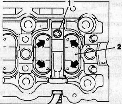
Mark the location and remove the rocker arms (2) from the cylinder head.
The alignment marks on the rocker arms (arrows) are located on the ends adjacent to the fuel rail.
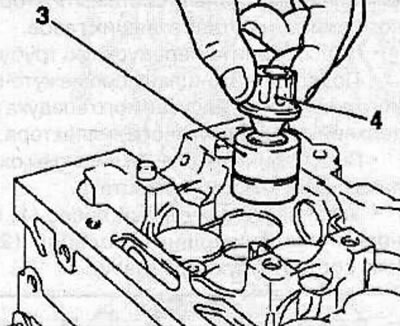
Using the special tool KM-845 (4), remove the hydraulic valve clearance compensators (3) from the cylinder head.
Remove the seals (6) from the fuel injectors.
Screw the KM-931 adapter (2) onto the fuel injector.
Install the KM-328-V puller (1) onto the adapter, then pull the fuel injector (3) out of the cylinder head.
Remove the lower sealing ring (4) from the fuel injector.
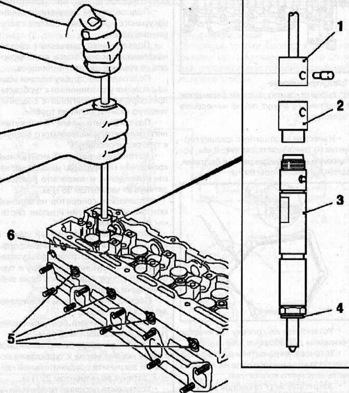
Using the special tool KM-980, remove the glow plugs (5) from the cylinder head.
Label the valves and mark their location in the cylinder head.
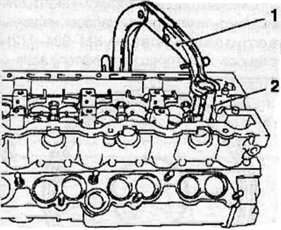
Using a special device KM-348 (1) with an adapter KM-653 (2), compress the valve spring and remove the crackers from the valve stem, the spring plate and the spring.
Using the special tool KM-840, remove the oil deflector cap and take out the valve spring support seat.
Remove the valve from the cylinder head.
Remove the remaining valves from the cylinder head in the same manner.
Clean all parts.
Check the mating surfaces of the cylinder head and the working surfaces of the valve guide bushings and plain bearings for wear.
Installation
Apply a coat of engine oil to the valve stems and install the valves into their places in the cylinder head.
Install the special bushing (2) on the valve stem and lubricate it with engine oil.
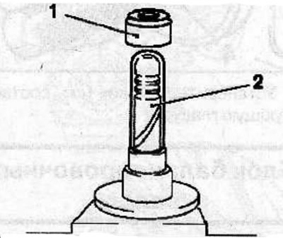
Install the valve spring support seat, then using the special KM-835-A device along a special bushing as a guide, install a new oil deflector cap (1).
Notes:
- Do not reuse previously removed valve stem seals.
- Incorrect installation of the valve stem seal will adversely affect its working edge due to eccentricity and will result in engine oil leakage through the valve guide.
Install the valve spring and spring retainer.
Using a special device KM-348 with an adapter KM-653, compress the spring. Install the crackers and remove the special spring compressor. Using a plastic hammer or hammer handle, tap the end of the valve stem several times to seat the crackers in place.
Install new O-rings (3 and 4) onto the fuel injectors.
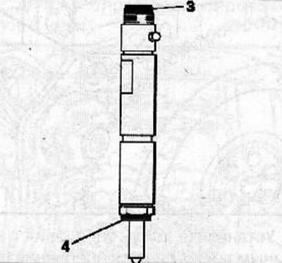
Install the fuel injectors into the cylinder head.
Using the special KM-980 tool, screw the glow plugs into the cylinder head and tighten them to a torque of 10 Nm.
Lubricate the hydraulic valve clearance compensators with engine oil and install them into the cylinder head in accordance with the markings made during removal.
Install a new sealing ring (1) on the fuel rail and lubricate it with a thin layer of silicone lubricant.
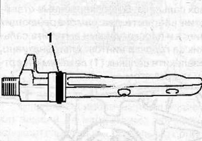
Install the fuel rail into the cylinder head, being careful not to damage the sealing ring.
Warning! Only this procedure for fastening the fuel rail ensures the correct fit of the rail on the injector.
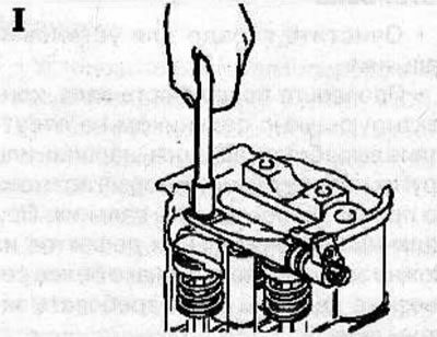
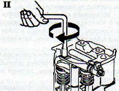
Secure the fuel rail with a new bolt and tighten it as follows:
I Hand tighten the bolt with the Torx head, do not use the wrench handle.
Material was taken from a resource [Opelbook.ru]
II Use the wrench to tighten the bolt through an angle of 360°.
Install the rocker arms into the cylinder head in accordance with the previously applied markings.
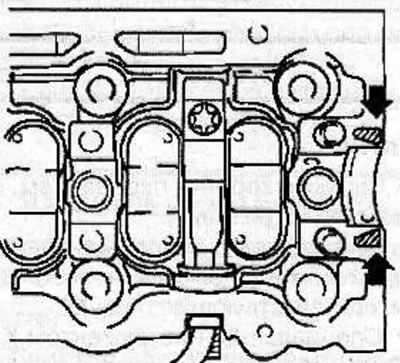
Apply a thin layer of sealant to the areas indicated by arrows in the figure.
Lubricate the contact surfaces of the tappets and camshaft with grease MoS2 and carefully install the camshafts back into place in the cylinder head.
Warning! When installing, the identification numbers on the camshaft bearing caps must match the numbers on the cylinder head.
Install the camshaft bearing caps and tighten their mounting bolts in a spiral pattern, following the sequence shown in the figure. First tighten all bolts by half a turn or a full turn, and then tighten them in the same sequence to a torque of 15 Nm.
Install the lower part of the intake manifold with a new gasket onto the cylinder head and secure with nuts, tightening them to a torque of 22 N·m.
Install the upper intake manifold with a new gasket onto the lower intake manifold and secure with bolts, tightening them to 8 Nm.
Install the exhaust manifold with a new gasket on the cylinder head and secure with nuts, tightening them to a torque of 22 N·m.
Install the generator bracket with a new gasket on the cylinder head and secure with the bolt, tightening it to a torque of 20 N·m.
Install engine lifting eyes on the cylinder head.
Install the cylinder head (see the relevant chapter).
Visitor comments