
Removing
1. Disconnect the negative battery terminal.
2. Drain the liquid from the engine cooling system.
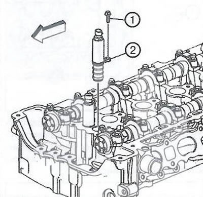
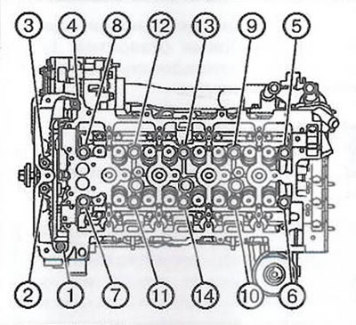
3. Loosen the bolt (1) and remove the solenoid valve (2) intake camshaft phase shifter.
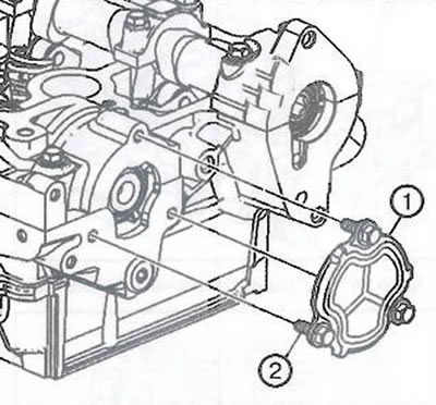
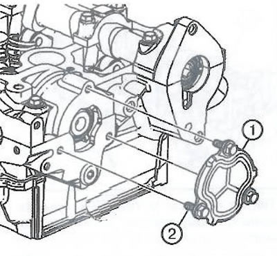
4. Loosen the screws (2) and remove the plate (1) rear opening of the cylinder head.
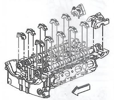
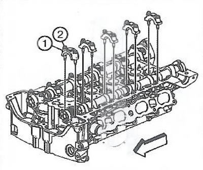
5. Turn away bolts of fastening and to remove a back cover of the bearing of an inlet cam-shaft.
6. Mark the intake camshaft bearing caps for proper alignment during reassembly.
Note. Loosen each bolt one turn at a time until the covers no longer spring back.
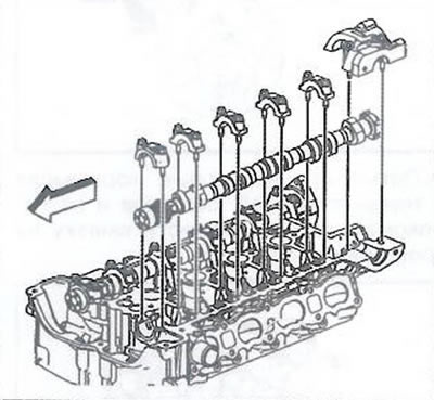
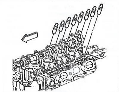
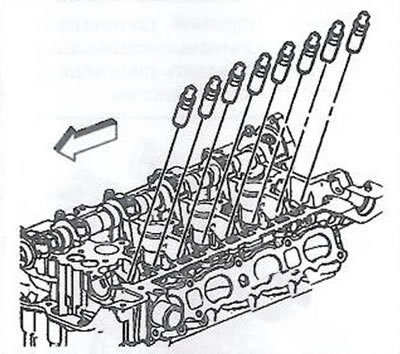
7. Remove the camshaft bearing caps.
8. Remove the intake camshaft.
9. Remove the intake camshaft roller tappets.
Note. Arrange all roller rocker arms and hydraulic lifters in order to put them in place during installation.
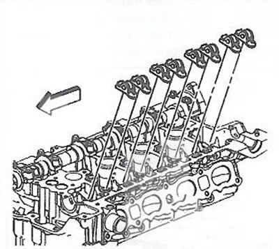
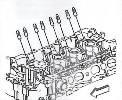
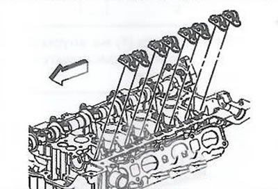
10. Remove the intake valve lifters.
11. Loosen the bolt (1) and remove the solenoid valve (2) exhaust camshaft phase shifter.

12. To turn away bolts of fastening and to remove a back cover of the bearing of a final cam-shaft.
13. Mark the exhaust camshaft bearing caps for proper installation during reassembly.
Note. Loosen each bolt one turn at a time until the covers no longer spring back.
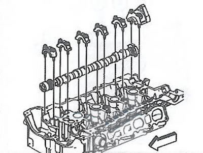
14. Remove the camshaft bearing caps.
15. To take a final camshaft.
16. Remove the intake camshaft roller tappets.
Note. Arrange all roller rocker arms and hydraulic lifters in order to put them in place during installation.
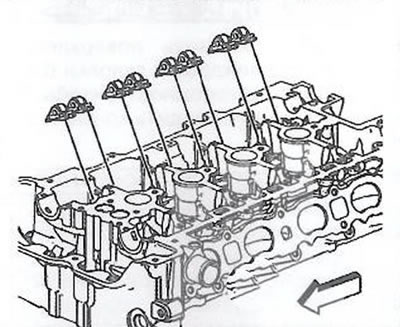
17. Remove the intake valve lifters.
18. Remove intake manifold.
19. Remove the exhaust manifold.
20. Remove the upper timing chain guide.
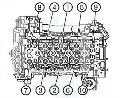
21. To turn away bolts of fastening of a head of the block of cylinders in the specified sequence.
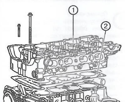
22. Remove the cylinder head (1) with gasket (2) from the cylinder block.
23. Use a spatula to clean the joint surfaces of the cylinder block and the block head. Be careful not to scratch or damage the contact surfaces.
Attention.
- Use a new spatula every time to clean the cylinder block and cylinder head.
- Do not use mechanical means to clean the joint surfaces.
- Be careful not to create gouges or scratches on the joint surfaces or combustion chamber. To ensure the tightness of the gasket, the condition of the joint surfaces is important. After removing the remnants of the old gasket, small depressions may remain on the surface, which will be filled when the new gasket is installed.
When removing the remnants of the old gasket, it is necessary to hold the spatula as parallel as possible to the surface to be cleaned.
24. Use a nylon brush to clean the threaded holes. If necessary, use solvent and compressed air.
Note. Do not use a tap to clean the threaded holes in the cylinder head.
Attention. Wear eye protection when using compressed air to clean holes.
25. If it is necessary to remove the shear bolt from the cylinder head, use the EN-38188 kit.
Installation
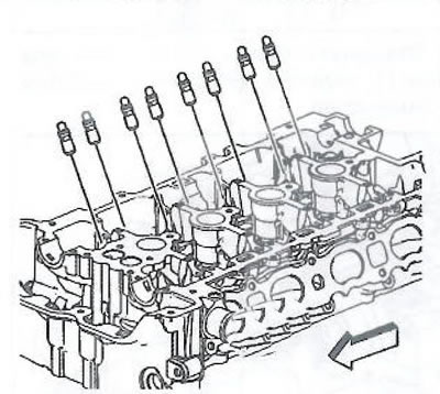
1. Install gasket (1) on the cylinder block (2), paying attention to the dowel pin (3) for proper gasket installation.
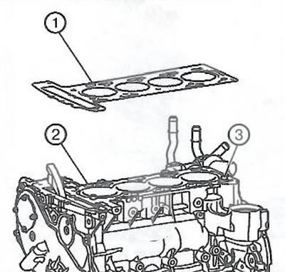
Note. Do not use sealants.
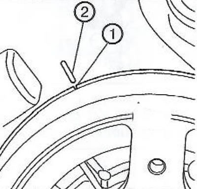
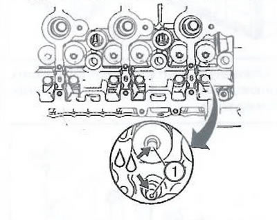
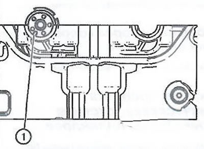
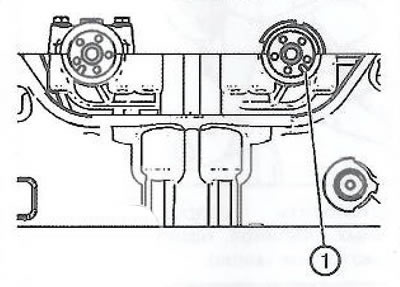
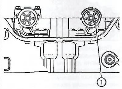
2. Make sure that the piston of the first cylinder is at top dead center. This requires that the label (1) on the balancer pulley of the crankshaft coincided with the mark (2) on the oil pump housing.
3. Install the cylinder head.
4. Install new cylinder head bolts.
Note. Always use new cylinder head bolts.
5. Tighten the cylinder head bolts in sequence to 30 Nm.
6. Tighten the cylinder head bolts an additional 155°using tool EN-45059.
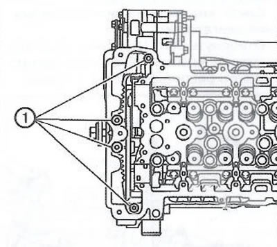
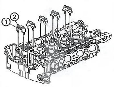
7. Install the front cylinder head bolts (1) and tighten to 35 Nm.
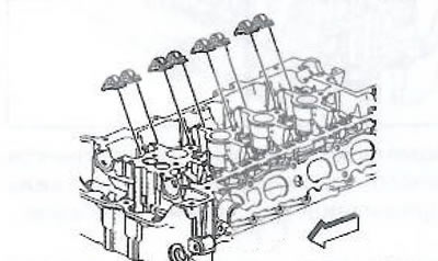
8. Install the exhaust valve lifters into their respective sockets in the cylinder head, applying clean engine oil to the lifters.
9. Lubricate the ends of the valve stems.
10. Place roller rocker arms on the ends of the valve stems and on the hydraulic lifters. Apply lubricant to the rocker arms.
Note. Used roller rocker arms must be reinstalled in their original positions. If the camshaft is to be replaced, the roller rocker arms must also be replaced with new ones.
11. When installing the exhaust camshaft, make sure that its groove (1) is at the 7 o'clock position. The number one piston should be at top dead center on the exhaust stroke and the crankshaft key should be at the 12 o'clock position.
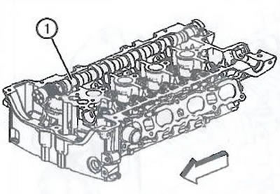
12. Install the exhaust camshaft (1) on roller rocker arms to the main bearings. Lubricate the camshaft with engine oil.
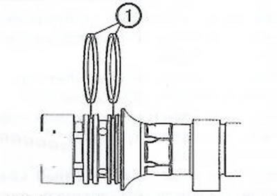
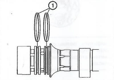
13. Before installing the camshaft main bearing caps, rotate the seals in the grooves of the first camshaft journal so that the joint line (1) was approximately at the 12 o'clock position.
14. Make sure the groove (1) on the exhaust camshaft is approximately at the 7 o'clock position.
15. Install the camshaft covers (1).
16. Apply to bolts (2) engine oil and screw them in three turns by hand, then tighten the bolts to 10 Nm.
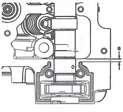
17. Apply a bead of sealant with a diameter of 2.5 mm to the cylinder head at the installation site of the rear cover of the exhaust camshaft bearing, without bringing the sealant to a distance «A» =2mm from the edge as shown in the picture.
Note
It is very important during installation to ensure that the rear camshaft bearing cap and cylinder head are correctly aligned so that they are at the same level. For this:
- Make sure that all sealant residues are removed from the components, sealing surfaces are clean and free of old sealant residues.
- Install and align rear camshaft bearing cap within 20 minutes of applying sealant.
18. To establish a back cover of the bearing of a final camshaft and evenly to tighten bolts of fastening at first the moment of 5 Nm, and then 10 Nm. Loosen bolts by 120°, then finally tighten to 10 Nm.
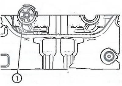
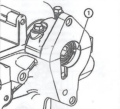
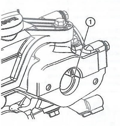
19. Remove all excess sealant from the hole (1) vacuum brake booster pump. Make sure the bore and contact surfaces are clean. Avoid excess sealant on cylinder head or contact surfaces.
20. Install the intake valve lifters with clean engine oil.
21. Lubricate the ends of the valve stems.
22. Place roller rocker arms on the ends of the valve stems and on the hydraulic lifters. Apply lubricant to the rocker arms.
Note. Used roller rocker arms must be reinstalled in their original positions. If the camshaft is to be replaced, the roller rocker arms must also be replaced with new ones.
23. When installing the intake camshaft, make sure that its groove (1) is approximately at the 5 o'clock position. The number one piston should be at top dead center on the exhaust stroke and the crankshaft key should be at the 12 o'clock position.
24. Install the intake camshaft on the roller rocker arms in the main bearings. Lubricate the camshaft with engine oil.
25. Before installing the camshaft main bearing caps, turn the seals in the grooves of the first camshaft journal so. so that the seam line (!) was approximately at the 12 o'clock position.
26. Make sure the groove (1) on the intake camshaft is approximately at the 5 o'clock position.
27. Install covers (1) camshaft.
28. Apply to bolts (2) engine oil and screw them in three turns by hand, then tighten the bolts to 10 Nm.
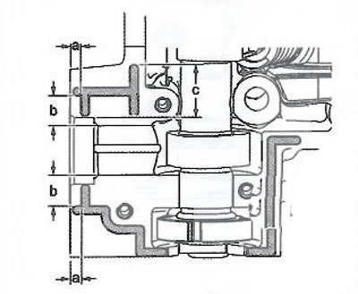
29. Apply a bead of sealant with a diameter of 2.5 mm to the cylinder head at the installation location of the rear bearing cover of the exhaust camshaft:
- Distance «A» =5 mm.
- Where the cap ends, extend the bead of sealant about 4mm beyond the cap.
- Distance «With» =32 mm.
- Distance «b» -20 mm.
Note
It is very important during installation to ensure that the rear camshaft bearing cap and cylinder head are correctly aligned so that they are at the same level. For this:
- Make sure that all sealant residues are removed from the components, sealing surfaces are clean and free of old sealant residues.
- Install and align rear camshaft bearing cap within 20 minutes of applying sealant.
30. Install the sixth rear camshaft cover. Tighten the fastening bolts evenly, first to 5 Nm and then to 10 Nm. Loosen bolts by 120°, then finally tighten to 10 Nm.
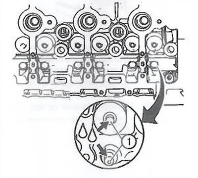
31. Remove all excess sealant from the hole (1) fuel pump drive. Make sure the bore and contact surfaces are clean. Avoid excess sealant on cylinder head or contact surfaces.
32. Remove excess sealant from the fuel pump mounting surface.
33. Make sure the mounting surfaces are clean, then install the plate (1) rear opening of the cylinder head and tighten the bolts to 10 Nm.
34. Install the upper timing chain guide.
35. Install the exhaust manifold.
36. Install the intake manifold.
37. Install the intake camshaft phase shift solenoid valve.
38. Install the exhaust camshaft phase shift solenoid valve.
39. Fill the engine cooling system.
40. Connect the negative battery terminal.
Visitor comments