


Removal
Remove the engine from the car (see the relevant chapter).
Remove the cylinder head (see the relevant chapter).
Remove the timing drive housing (see the relevant chapter).
Remove the clutch housing with the pressure plate and the driven clutch disc (see the relevant chapter).
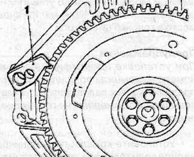
Using the special tool KM-652 (1), block the flywheel from turning and unscrew its mounting bolts.
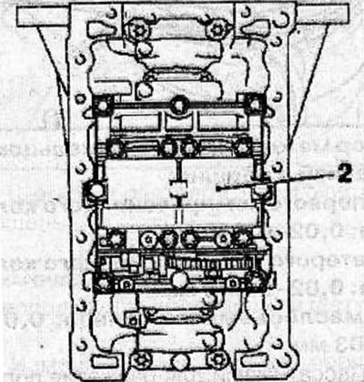
Remove the balance shaft block (2) (see the relevant chapter).
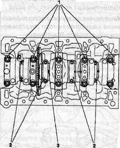
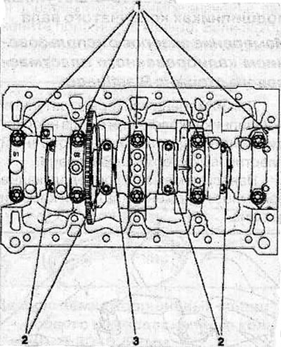
Mark the crankshaft main bearing caps (1) and the connecting rod caps (2), making sure that the protrusion (3) on the connecting rod is on the flywheel side.
Remove the bolts and the connecting rod caps.
Remove the bolts and remove the crankshaft main bearing caps from the cylinder block.
Remove the crankshaft from the cylinder block.
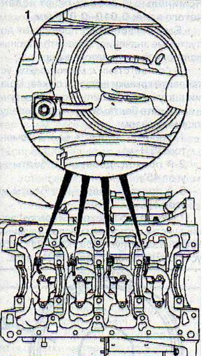
Remove the bolts and engine oil sprayers (1) from the cylinder block (see picture on next page).
Examination
Clean all parts thoroughly.
Check the crankshaft main and connecting rod journals for scratches, wear or cracks. Check the crankshaft oil holes for clogging
Lubricate the main bearing shells with engine oil and install them into the cylinder block.
Install the crankshaft onto the main bearing shells in the cylinder block.
Install the measuring tip of the MKM-571-V pointer-type indicator onto the crankshaft main journal. Rotate the crankshaft and measure its runout using a pointer-type indicator.
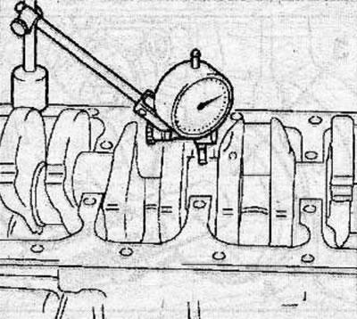
Crankshaft runout: no more than 0.03 mm
Warning: Use new bolts to secure the crankshaft main bearing caps.
Measuring clearances in crankshaft main bearings
Measuring gaps using a calibrated plastic rod Plastigage
To measure the crankshaft bearing clearance, use a calibrated plastic Plastigage rod.
Loosen the bolts and remove the cover and main bearing shell. Clean the bearing, cover and crankshaft journal.
Cut a piece of Plastigage plastic gauge rod the same length as the bearing width and place it along the crankshaft axis on the main bearing journal.
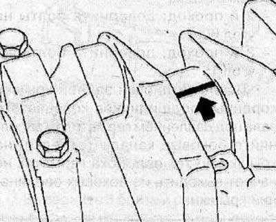
Install the main bearing cap with the liner and secure it with bolts, tightening them as follows:
- 1st pass: tighten the bolts to 90 Nm;
- 2nd pass: tighten the bolts to an angle of 60°;
- 3rd pass: tighten the bolts by an additional 15°.
Note: When checking main bearing clearances, the main bearing cap bolts can be reused.
Warning: When measuring clearances using a Plastigage gauge, do not rotate the crankshaft.
Loosen the bolts and remove the main bearing cap again. Compare the width of the deformed Plastigage plastic rod with the measuring scale printed on the plastic rod packaging. Use the scale to determine the gap.
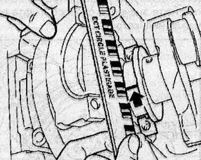
Nominal clearance in the crankshaft main bearing: 0.016-0.069 mm
Install the main bearing cap with the liner and secure it with bolts, tightening them as follows:
- 1st pass: tighten the bolts to 90 Nm;
- 2nd pass: tighten the bolts to an angle of 60°;
- 3rd pass: tighten the bolts by an additional 15°.
Measuring clearances using a bore gauge and micrometer
Note: To measure main bearing clearances using a bore gauge and micrometer, the crankshaft must be removed from the engine.
Install the main bearing shells into the cylinder block and main bearing cap.
Install the main bearing cap with the liner and secure with bolts, tightening them as follows:
- 1st pass: tighten the bolts to 90Nm;
- 2nd pass: tighten the bolts to an angle of 60°;
- 3rd pass: tighten the bolts by an additional 15°.
Note: When checking main bearing clearances, the main bearing cap bolts can be reused.
Using a bore gauge, measure the inner diameter of the crankshaft main bearing in three places I, II and III.
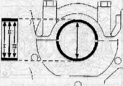
Calculate the average bore diameter of the main bearing using the formula:
Average bore diameter of main bearing = (I + II + III): 3
Information taken from the website: Opelbook.ru
Example:
- I = 54.972 mm
- II = 54,981 mm
- III = 54,984 mm
Average bore diameter of main bearing = (54.972 + 54.981 + 54.984): 3 = 54.979 mm
Using a micrometer, measure the diameter of the crankshaft main journal in two diametrically perpendicular planes.
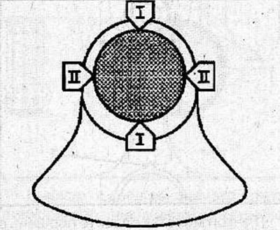
Calculate the average diameter of the crankshaft main journal using the formula:
Average diameter of crankshaft main journal = (I + II): 2
Example:
- I = 54,962 mm
- II = 54,964 mm
Average diameter of crankshaft main journal = (454.962 + 54.964): 2 = 54.963 mm
Calculate the clearance in the crankshaft main bearing by subtracting the average diameter of the crankshaft main journal from the average diameter of the main bearing bore.
Nominal clearance in the crankshaft main bearing: 0.016-0.069 mm
Installation
Install the engine oil sprayers into the cylinder block and secure with bolts, tightening them to a torque of 22 N·m.
Lubricate the main bearing shells with engine oil and install them into the cylinder block and main bearing caps.
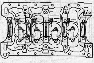
Install the crankshaft onto the main bearing shells in the cylinder block.
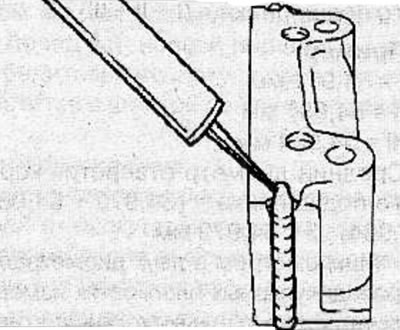
Before installing the rear crankshaft main bearing cover, fill the side channels on the cover with sealant.
Install the crankshaft main bearing caps in accordance with the markings and secure with bolts, tightening them as follows:
- 1st pass: tighten the bolts to 90 Nm;
- 2nd pass: tighten the bolts to an angle of 60°;
- 3rd pass: tighten the bolts by an additional 15°.
After installing the crankshaft main bearing rear cover, pressurize the side channels (arrows) on the cover with sealant until sealant begins to come out of the side joints of the cover.
Turn the crankshaft and check that it rotates easily and smoothly.
Check the crankshaft axial clearance. Install the measuring tip of the MKM-571-V pointer-type indicator on the rear end of the crankshaft. Move the crankshaft along the axis until it stops and set the dial indicator scale to zero. Move the crankshaft along the axis in the other direction until it stops and read the axial play values on the indicator scale.
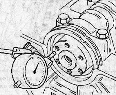
Nominal axial clearance of the crankshaft: 0.010-0.020 mm
If the axial clearance exceeds the permissible values, replace the crankshaft thrust washers.
In accordance with the markings, install the connecting rod caps with connecting rod bearing shells on the connecting rods and secure with bolts, tightening them as follows:
- 1st pass: tighten the bolts to 35 Nm;
- 2nd pass: tighten the bolts to an angle of 45°;
- 3rd pass: tighten the bolts by an additional 15°.
Lubricate the working edges of the new oil seal with clean engine oil, slide it onto the protective sleeve KM-934-1 (2) and install it on the end of the crankshaft.
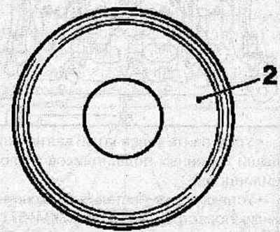
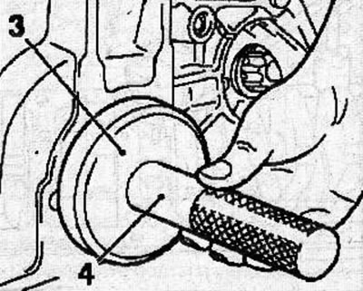
Using special tools KM-934-2 (3) and KM-454-4 or KM-523-2 (4), press the oil seal into place.
Install the flywheel onto the crankshaft.
Using the special tool KM-652 (2), block the flywheel from turning.
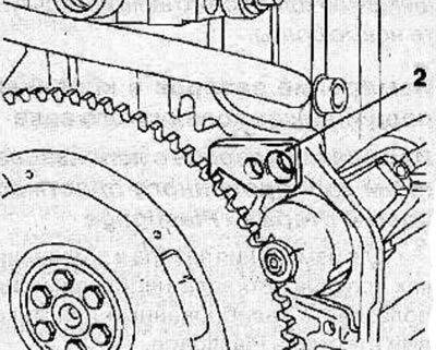
Tighten the new flywheel mounting bolts as follows:
- 1st pass: tighten the bolts to 45 Nm;
- 2nd pass: tighten the bolts by 30°;
- 3rd pass: tighten the bolts by an additional 15°.
Install the balance shaft block (see the relevant chapter).
Install the timing drive housing (see the relevant chapter).
Install the cylinder head (see the relevant chapter).
Install the engine into the car (see the relevant chapter).
Visitor comments