
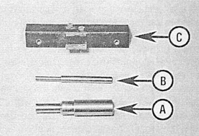
And — a rod of fixing of a cranked shaft (equivalent of special tool KM-929)
B - The fixing rod of the injection pump flange (equivalent of special tool KM-927)
C - Camshaft Locking Tool (equivalent of special tool KM-932)
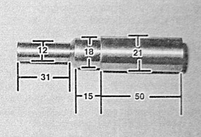
Dimensional specifications of the crankshaft locking tool (mm)
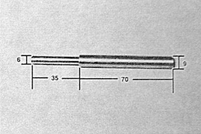
Dimensional characteristics of the injection pump flange locking device (mm)
The following Opel special tools are required to carry out these checks (or their equivalents):
- 1. camshaft locking tool (KM-932)
- 2. device for blocking the injection pump flange (KM-927)
- 3. crankshaft locking tool (KM-929)
- 4. camshaft sprocket lever (KM-933).
If necessary, a suitable tool can be made in-house by an amateur mechanic in accordance with the dimensional specifications presented.
Using a camshaft locking tool, the groove in the camshaft journal is fixed parallel to the mating surface of the cylinder head.
1. Disconnect the negative cable from the battery. Remove the accessory drive belt (see chapter Current service). Turn out the bottom bolt of fastening of a rack of a tension roller and an axial bolt of the basis of a tensioner. Remove the tensioner assembly from the engine.
Do not remove the rack from the tensioner assembly, otherwise it will be necessary to grind the working surfaces.
2. Remove the brake booster servo vacuum pump (see chapter Brake system).
3. In order to facilitate access to the injection pump sprocket cover and to the pump, perform the following preparatory operations:
4. Remove the air cleaner housing and exhaust pipe, (see chapter Power and exhaust systems).
5. Mark the position of the right power unit mount bracket relative to the cylinder head bracket. Remove the three bolts securing the right engine mount to the head bracket and the three bolts securing the engine mount to the mudguard. Support the right side of the engine with a trolley jack. Raise the engine as high as possible without overloading the remaining supports and communication lines (tubes, hoses, wiring harnesses).
- Remove the timing cover (see Removal and installation of a cover of the gas-distributing mechanism) and bring the piston of the first cylinder to the TDC position of the end of the compression stroke (see Bringing the piston of the first cylinder to the position of the top dead center of the end of the compression stroke (TDC).
- Remove crankshaft position sensor (CKP) (see chapter Power and exhaust systems).
- Unscrew the fixing bolts and remove the injection pump sprocket cover from the timing chain cover.
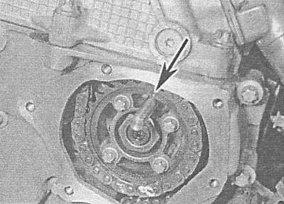
7. Make sure that the risk on the crankshaft pulley is aligned with the alignment mark on the timing chain cover and thread the fixing rod into the hole for installing the CKP sensor, engaging it with the cutout in the shaft body.
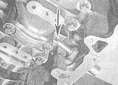
8. With the crankshaft blocked, thread the fixing rod through the hole in the injection pump flange and push its end into the hole in the pump.
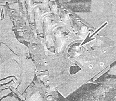
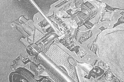
9. Then fill the camshaft locking tool into the groove in the camshaft trunnion.
10. If all the fixing devices freely fall into their regular places, therefore, the gas distribution phases are set correctly and no adjustment is required, proceed to the procedures (see paragraph below. 22-27) . If at least one tool cannot be installed properly, adjust accordingly (see below), - pay attention to the need to replace the crankshaft sprocket bolt and tensioner bolt O-ring.
11. Remove the devices that block the camshaft and the injection pump flange, unscrew the bolts securing the right support bracket to the cylinder head.
12. Remove the upper timing chain tensioner cap from the back of the cylinder head and remove the plunger - try to remember its installation position. Remove the o-ring and discard it - the ring must be replaced without fail during installation.
13. Holding the camshaft by the flats with an open-end wrench, release and remove the sprocket mounting bolt. Screw in a new bolt and tighten it until hand-tight.
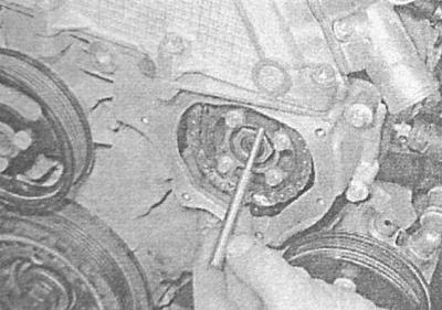
14. Loosen the bolts securing the injection pump sprocket to the pump flange.
15. Having blocked the crankshaft from turning, make sure that the TDC mark on the upper timing chain sprocket is aligned with the hole for monitoring the valve timing in the injection pump flange. Pass the fixing rod and tighten the sprocket mounting bolts to the required torque.
16. Push the end of the camshaft blocking rod into the groove on the end of the camshaft trunnion, aligning the guide pin with the hole.
17. Having installed the fixing devices in their regular places, install the camshaft sprocket lever - if there is no lever, use two bolts by threading them into the sprocket holes. Then, using a large screwdriver as a lever, block the sprocket from turning. Have a second person hold the upper side of the timing chain taut - apply a little force to the sprocket, leaving all the slack in the chain on the tensioner side.
18. After tightening the upper chain, make sure that the injection pump fixing rod moves in its hole with little resistance. When biting the rod, ask the assistant to ease the pressure on the sprocket - if the rod moves too freely, the force should be slightly increased.
19. Having tensioned the upper chain as required, fix the camshaft with an open-end wrench and tighten the bolt of its sprocket with the force of the 1st stage. Check the freedom of movement of the fixing injection pump rod, then tighten the sprocket mounting bolt to the angle, first the 2nd, then the 3rd stages of tightening - use a goniometric attachment to the wrench, or apply reference marks with a marker.
20. Remove all locking devices and install a new O-ring on the upper timing chain tensioner cap. Insert the plunger into the cylinder head (blind end to the chain), install the cap and tighten it to the required torque.
When installing a new tensioner, loosen it, completely drowning the central rod of the cap until it clicks - now the tensioner rod should sink freely and smoothly return to its original position.
21. Turn the crankshaft two full two turns (720°) in the normal direction (see Bringing the piston of the first cylinder to the position of the top dead center of the end of the compression stroke (TDC), in order to bring the piston of the first cylinder to the TDC of the end of the compression stroke, - make sure that all fixing devices can be easily installed.
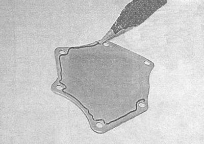
22. Make sure that the mating surfaces of the injection pump sprocket and timing drive covers are absolutely clean and dry. If the cover was originally installed on the gasket, replace the latter. Tighten the cover bolts to the required torque. If a gasket was not provided, apply a cushion of sealant approximately 2 mm thick to the mating surface of the cover, install the cover and tighten the bolts of its fastening with the required force.
23. Install the accessory drive belt tensioner on the engine, tightening both bolts to the required torque. If the riser was removed from the tensioner assembly, lap it in several successive reciprocating motions, placing the head on the hex part of the base. If the rack functions properly, install the accessory drive belt (see chapter Current service).
24. If removed, install the bracket of the right power unit suspension support on the cylinder head and remove the jack supporting the engine. Install the right support on the mudguard and align it with the marks made during the dismantling process on the cylinder head bracket. Screw fixing bolts and tighten them with the required effort. Install the timing cover (see Removal and installation of a cover of the gas-distributing mechanism).
25. Reinstall the downpipe of the exhaust system and the air cleaner housing (see chapter Power and exhaust systems).
26. Install the brake booster servo vacuum pump on the cylinder head (see chapter Brake system).
27. Install the CKP sensor on the cylinder block (see chapter Power and exhaust systems) and connect the negative wire to the battery.
Visitor comments