


Contents: Camshaft gear ⬇ Fuel injection pump gear wheel ⬇ Crankshaft gear ⬇ Oil pump gear (dOHC engines) ⬇ Tensioner assembly ⬇ Intermediate roller ⬇
Camshaft gear
Removal
SOHC engines
1. Remove the timing belt (see Removal and installation the timing belt).
2. Remove the timing cover (see Removal and installation the timing cover).
3. Secure the camshaft from turning by holding it with an open-end wrench by the hex section. Unscrew the mounting bolt and remove the camshaft gear.
DOHC engines
1. Remove the timing belt (see Removal and installation the timing belt). Before loosening the timing gear mounting bolt, turn the crankshaft 60° back from the TDC position to prevent the valves from coming into contact with the pistons.
2. To prevent the camshaft from turning, fully tighten the timing gear lock bolt.
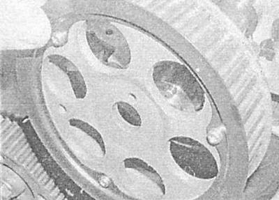
3. Loosen the locking bolt and remove the toothed wheel from the camshaft journal - try to remember the installation position of the components. If the toothed wheel locking rod has a loose fit, remove it from the camshaft and put it in a safe place.
Installation
SOHC engines
A new camshaft timing gear bolt will be required!
1. Install the gear, screw in the NEW mounting bolt and tighten it finger tight only for now.
2. Install the timing belt (see Removal and installation the timing belt).
DOHC engines
1. Make sure that the locking rod is in its proper place, then install the gear wheel on the camshaft, making sure that the locking rod enters the mating hole.
2. Screw in the gear mounting bolt, then align the mounting holes in the gear and head and screw in the M6 bolt. Tighten the gear mounting bolt to the required torque. Turn the crankshaft 60° clockwise until the mark on the crankshaft gear is at the 12 o'clock position and aligned with the cast mark on the oil pump cover.
3. Install the timing belt (see Removal and installation the timing belt).
Fuel injection pump gear wheel
Removal
SOHC engines
1. Remove the timing belt (see Removal and installation the timing belt).
2. Insert the KM-6011 device into the hole to fix the flange in order to prevent the fuel injection pump gear from turning. If you do not have a special device at hand, use a rod with a diameter of 9.5 mm and a length of 75 mm.
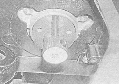
3. Remove the three mounting bolts and remove the gear wheel.
DOHC engines
1. Remove the timing belt (see Removal and installation the timing belt).
2. To prevent the injection pump shaft from turning all the way, screw in the M8 bolt that secures the gear wheel.
If necessary, the gear wheel can be locked in another way: using a device in the form of a fork with bolts screwed into the ends and equipped with locking nuts.
3. Loosen and unscrew the gear wheel mounting nut.
4. Remove the gear wheel from the injection pump shaft — try to remember the installation position of the components. If the key has a weak fit in the injection pump shaft journal, remove it and put it in a safe place.
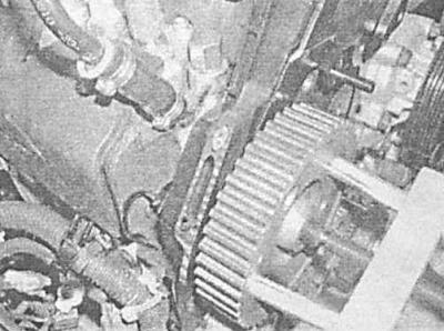
The gear has a tapered fit on the shaft journal and in some cases a puller may be required to remove it.
Installation
SOHC engines
1. Place the gear wheel on the pump shaft, making sure that the cutout on the sprocket is aligned with the cutout on the flange and the hole for inserting the KM-6011 locking rod.
2. Screw in the gear mounting bolts and tighten them only by hand for now.
3. Install the timing belt (see Removal and installation the timing belt).
DOHC engines
1. Make sure that the key is correctly seated in the shaft journal, then install the gear wheel - make sure that the key fits into the keyway.
2. Screw on the fastening nut and tighten it to the required force, blocking the gear wheel from turning by screwing in the M8 fixing bolt.
3. If a fork-type device was used to secure the sprocket, align the mounting holes and screw in the M8 bolt.
4. Install the timing belt (see Removal and installation the timing belt).
Crankshaft gear
Removal
SOHC and DOHC engines
1. Remove the crankshaft pulley (see Removal and installation the crankshaft pulley).
2. On models with manual transmission ask an assistant to engage the highest gear and fully depress the foot brake pedal in order to block the crankshaft from turning models with AT unscrew one of the torque converter mounting bolts and tighten the latter to the transmission housing using a steel bar and suitable bolts with washers (see Chapter Automatic transmission). If the engine is removed from the vehicle, the flywheel/drive plate must be locked (see Removal, checking condition and installing flywheel/drive disk). Loosen the gear mounting bolt.
3. Remove the timing belt (see Removal and installation the timing belt).
4. Unscrew the fastening bolt with the washer and remove the toothed wheel - if the wheel does not give in, use a suitable puller. If the key fits freely in the shaft journal, remove it and put it in a safe place.
5. On dOHC engines remove the flange spacer from the crankshaft journal - try to remember the installation position of the components.
Installation
SOHC and DOHC engines
1. Installation is carried out in the reverse order of dismantling the components - ensure that the key is correctly seated in the shaft journal and that the keyway of the gear hub is correctly aligned with it.
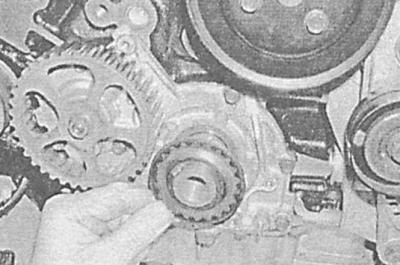
On DOHC engines, the flange spacer is installed with the protruding side facing out.
Oil pump gear (dOHC engines)
Removal
1. Remove the timing belt (see Removal and installation the timing belt).
2. Having blocked the oil pump gear from turning using a replaceable socket head with an extension placed on one of the oil pump cover mounting bolts, unscrew the central gear mounting bolt.
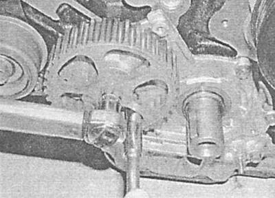
3. Remove the gear from the oil pump shaft, try to remember the installation position of the components.
Installation
1. Install the gear wheel, making sure that the keyway is correctly aligned with the key. Tighten the nut with the required force, blocking the gear wheel from turning the sprocket in the same way as when removing it.
2. Install the timing belt (see Removal and installation the timing belt).
Tensioner assembly
Removal
SOHC engines
1. Remove the timing belt (see Removal and installation the timing belt).
2. Remove the mounting bolt and remove the tensioner assembly from the engine.
DOHC engines
1. Remove the timing belt (see Removal and installation the timing belt).
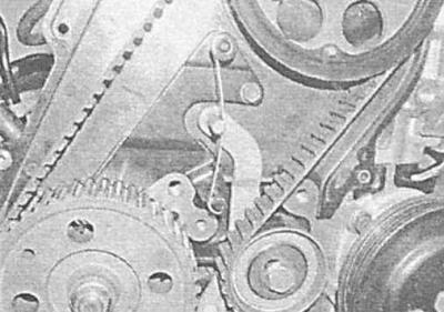
2. Carefully release the tension spring, then remove the mounting bolts and remove the tensioner assembly.
Installation
SOHC and DOHC engines
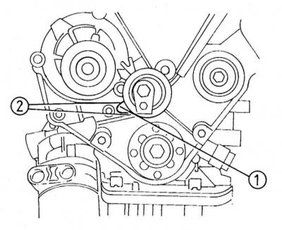
1. Installation is performed in the reverse order of component removal. On SOHC engines, ensure that the guide lever (1) is aligned with the corresponding cutouts in the oil pump cover (2).
On SOHC engines, final tightening of the tensioner mounting bolt is performed after the timing belt is installed.
Intermediate roller
Removal
SOHC and DOHC engines
1. Remove the timing belt (see Removal and installation the timing belt).
2. Unscrew the mounting bolt and remove the roller from the engine.
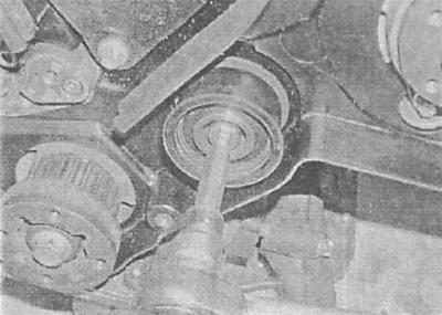
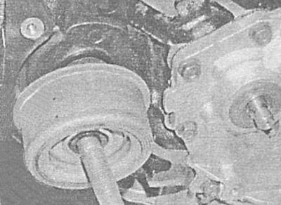
On SOHC engines, the intermediate roller is removed together with the spacer.
Installation
SOHC and DOHC engines
Installation is performed in the reverse order of dismantling the components. Make sure that the fasteners are tightened to the required force.
Visitor comments