
Removing
Do not allow dirt to enter the power supply system and injection pump!
The dismantling of the head must be carried out with a completely cooled engine. Prepare a new cylinder head gasket in advance.
Engines 1.7 l SOHC
1. Disconnect and remove the battery (see chapter Engine electrical equipment).
2. Empty the cooling system. Unscrew the fixing bolts and remove the air cleaner assembly with air ducts and air mass meter (see chapter Cooling, heating systems).
3. Disconnect the generator from the adjusting bar and the upper rear support bracket. Loosen the lower alternator mounting bolt, remove the alternator drive belt and turn the alternator back.
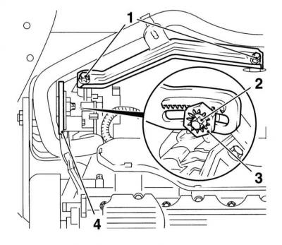
1 — Bolts of fastening of the top bracket
2 - Adjusting bolt
3 — Nut of an adjusting bolt
4 - Adjusting bar
4. Remove the timing cover (see Removal and installation of a cover of the gas-distributing mechanism).
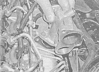
5. Unclip the air hoses between the turbocharger and intercooler and intercooler and intake manifold (see chapter Power and exhaust systems).
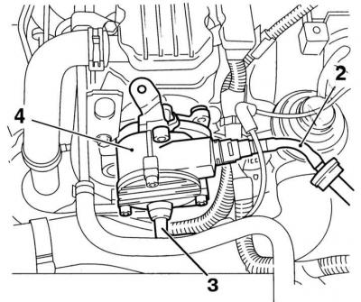
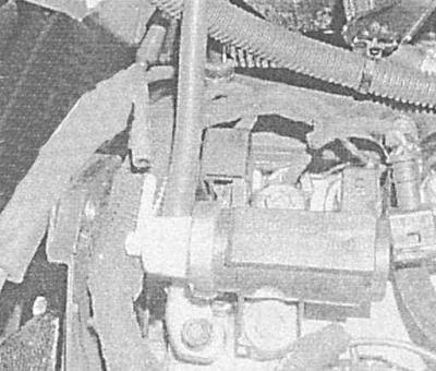
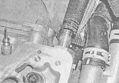
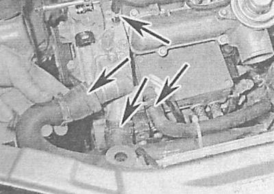
6. Disconnect from the vacuum pump (4) on the left side of the timing housing, the brake booster servo tube and vacuum line (2) And (3).
7. Disconnect wiring from coolant temperature sensor, boost pressure sensor, and EGR solenoid valve.
8. Disconnect the electrical wiring from the timing case and take it aside.
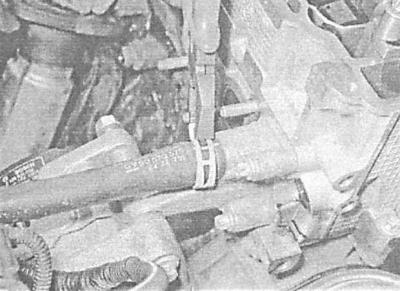
9. Loosen the mounting clamps and disconnect the upper radiator hose from the pipes on the flange and radiator.
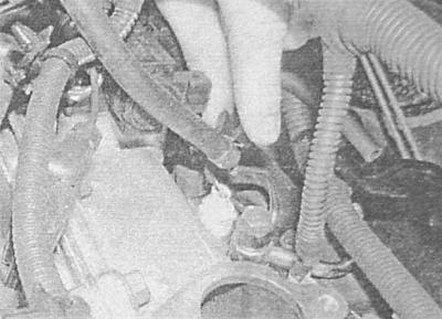
10. Disconnect the fuel supply and return lines from the timing case.
11. Release collars and disconnect a hose of a broad tank from the top forward branch pipe of the case of the thermostat and the case of the gas-distributing mechanism. Take the hose aside.
12. Remove the fasteners between the fuel lines - try to remember the installation position of the components.
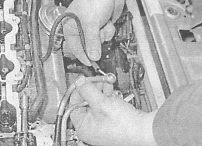
13. Clean the nipple connectors of the injectors and injection pump outlet (4 pieces), then loosen their union nuts. When loosening the nuts of the injection pump fittings, hold the fittings from turning with the second wrench. After loosening the nuts, remove the fuel pipes from the engine one by one. Use a clean rag to pick up spilled fuel. Seal nozzles, fittings, and tubing tips with clean plastic plugs to prevent dirt from entering the power system. Disconnect the fuel return line from the first injector.
14. Give two nuts and disconnect an electroconducting from glow plugs of the 2nd and 3rd cylinders.
15. Release the nipple connector and disconnect the turbocharger oil supply pipe from the cylinder block (see chapter Power and exhaust systems).
16. Disconnect the oil feed pipe from the turbocharger (see chapter Power and exhaust systems).
17. Turn out a fixing bolt and disconnect a returnable oil pipe of a turbocharger from the top part of the pallet crankcase. Remove sealing washers.
18. Disconnect the exhaust manifold support bracket from the cylinder block and exhaust manifold. Turn out fixing nuts and disconnect a reception pipe of system of release of the fulfilled gases from a final collector.
19. Turn out a fixing bolt and disconnect a basic arm of electroconducting and pipes of return of fuel from the left back part of a head of cylinders.
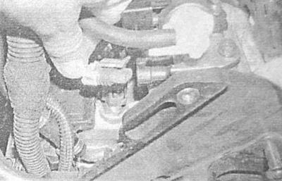
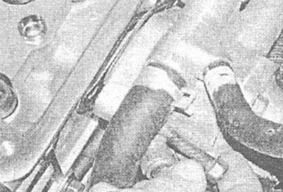
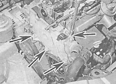
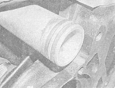
20. Turn out two fixing bolts and remove the thermostat case from the right back part of a head of cylinders. Separate the casing from the metal cooling pipe at the rear of the cylinder block - pay attention to the two o-rings, and take it to the side along with the heater hose.
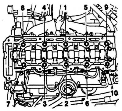
21. Acting in the reverse order of that indicated, gradually, half a turn per approach, evenly loosen the ten head mounting bolts until they can be released manually.
22. Remove the head mounting bolts along with the washers.
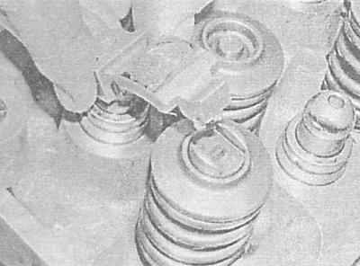
23. Remove the timing case from the head, prepare eight clean plastic bags or plastic cups and label them according to the numbering of the valves. Remove the valve drive levers, fixing their shaped washers and hydraulic lifters, - arrange the components in bags / cups in accordance with the markings.
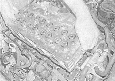
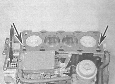
24. Having resorted to the help of an assistant, remove a sufficiently heavy cylinder head from the block. Remove the gasket, - try not to lose the two guide bushings installed in the cylinder block. If the bushings are loose and easy to remove, remove them and put them in a safe place. Do not throw away the old gasket - it can be used as a reference when purchasing a new one.
For a description of the procedure for disassembling the cylinder head in case it is necessary to carry out a refurbishment, see. General and overhaul of the engine.
Engines 1.7 L DOHC
1. Empty the cooling system. Unscrew the fixing bolts and remove the air cleaner assembly with air ducts and air mass meter (see chapter Cooling, heating systems).
2. Remove the camshaft gear (see Removal and installation of the belt tensioner and timing gears (engines 1.7 l).
3. Turn out and bolts of fastening of a back cover of gas-distributing GRM to the case of the gas-distributing mechanism and a head of the block.
4. Remove the timing case (see Removal and installation of the gas distribution mechanism housing (1.7L DOHC engines), remove the camshafts. Prepare 16 clean plastic bags or plastic cups and label them according to the valve numbers. Remove the tappets from their seats in the cylinder head and put them together with the adjusting washers in appropriately labeled bags / cups.
5. Turn out three fixing bolts and remove the thermofilter from a final collector.
6. Turn out bolts and nuts of fastening of a final collector to a head of cylinders. Remove washers. Using a TORX socket, unscrew the two manifold mounting studs and pull the manifold off the engine. An alternative way to dismantle the exhaust manifold is described in Chapter Power and exhaust systems.
7. Turn out fixing bolts and remove valve EGR.
8. Disconnect the fuel pipes from the injectors (see chapter Power and exhaust systems).Wipe clean the outlet connectors of the injection pump (4 pieces), then loosen their union nuts. When loosening the nuts of the injection pump fittings, hold the fittings from turning with the second wrench. After loosening the nuts, remove the fuel pipes from the engine one by one. Use a clean rag to pick up spilled fuel. Seal nozzles, fittings, and tubing tips with clean plastic plugs to prevent dirt from entering the power system. Disconnect the fuel return line from the first injector.
9. Disconnect the vacuum hose and wiring connector from the EGR solenoid valve.
10. Disconnect the fuel return hose from the injection pump.
11. Disconnect the wiring from the boost pressure sensor, installed behind the EGR valve on the intake manifold.
12. Disconnect the electrical wiring from the glow plugs (see chapter Engine electrical equipment).
13. Release a collar and disconnect a hose of system of cooling from the left back part of a head of cylinders.
14. Disconnect the electrical wiring from the coolant temperature sensor. Turn out fixing bolts and remove the case of the thermostat from the left back part of a head of cylinders.
4. Acting in the reverse sequence to that indicated, gradually, half a turn per approach, evenly loosen the ten head mounting bolts until they can be released manually.

5. Remove head bolts along with washers.
6. Having resorted to the help of an assistant, remove a sufficiently heavy cylinder head from the block. Remove the gasket, - try not to lose the two guide bushings installed in the cylinder block. If the bushings are loose and easy to remove, remove them and put them in a safe place. Do not throw away the old gasket - it can be used as a reference when purchasing a new one.
For a description of the procedure for disassembling the cylinder head in case it is necessary to carry out a refurbishment, see. General and overhaul of the engine.
Engines 2.0 l
1. Empty the cooling system (see chapter Cooling, heating systems).
2. Follow the steps above (see Removal and installation of a camshaft (ov) and valve drive components — Withdrawal, Engines 2.0 l - pp. 1-13), - note that a trolley jack is required to lift the engine, - place a block of wood between the jack head and the sump to distribute the load.
3. Wipe clean the fuel hose connections, unscrew the nipple bolts and remove the sealing washers. Disconnect the fuel return hose from the pump, release the hoses from the intermediate clamps and take them away from the head.

4. Remove the intake piping and exhaust manifold (see chapter Power and exhaust systems). If the head cannot be repaired, it can be removed complete with pipeline and manifold:
5. On high pressure turbocharged models, remove the intake ducts and metal tube from the turbocharger.
6. Turn out bolts of fastening of a routing trench of an electroconducting to the top part of the inlet pipeline and take away it aside from the engine. Disconnect the piping harness of the crankshaft position sensor (CKP);
7. Remove the fuel pipes going from the injection pump to the injectors. Disconnect the vacuum hoses from the intake manifold switching valve and the EGR valve;
8. Disconnect the electrical wiring from the glow plugs and remove the turbocharger heat shield;
9. Disconnect the turbocharger oil pipes from the cylinder block. Disconnect the diaphragm vacuum hose;
10. Remove the starter heat shield. Remove the mounting bolts and remove the wiring guide and exhaust manifold support bracket from the rear of the cylinder block.
5. Release collars and disconnect hoses of system of cooling from forward and back parts of the left wall of a head of cylinders.
6. Turn out the top fixing bolt and take away the generator from a head of cylinders.
7. Turn out three bolts of fastening of the right side of a head of cylinders to the top part of a cover of a gas-distributing chain and a single bolt of fastening of a head to the block.
8. Acting in the reverse order of that indicated, gradually, half a turn per approach, loosen the ten main bolts of the head fastening so that it becomes possible to turn them out by hand.

9. Remove bolts complete with washers.
10. With the help of an assistant, lift the head and remove it from the engine. Remove the seal. Pay attention to the two guide bushings mounted on top of the cylinder head - if the bushings have a loose fit, remove them and put them in a safe place. It would be wise to keep the old gasket in order to identify the new one by it.
Do not place the head on the bottom mating surface, place wooden blocks under the head so that they do not touch the glow plugs or injector nozzles, which protrude from the head plane and can be damaged if the head is placed directly on the workbench.
For cylinder head reconditioning procedures, see General and overhaul of the engine.
Preparing for installation
All engines
1. Thoroughly clean and dry the mating surfaces of the head and cylinder block. Use a hard plastic or wood scraper to remove all traces of old gasket material and carbon deposits. Also clean the piston bottoms. Be extremely careful - surfaces are easily damaged. Remember that dirt should not get into the oil channels, water galleries, channels and threaded holes - plug them with plugs or seal them with tape. To prevent deposits from getting into the gaps between the pistons and cylinders, fill the last with a thick lubricant, which, after cleaning, can be easily removed with a stiff brush. After cleaning, wipe all surfaces with a clean, dry cloth.
2. Inspect the mating surfaces of the head and block for deep scratches, cracks, or other damage. Minor defects can be eliminated with a small scraper, in more serious cases, the head should be machined or replaced.
3. Make sure the threaded holes are clean and dry - just in case, blow them out with compressed air (you can use a bicycle pump). The presence of traces of grease in the blind holes can lead to the destruction of the block when the bolts are tightened as a result of the increase in hydraulic pressure.
4. Head bolts must be replaced without fail, regardless of their current condition.
5. Using a steel ruler and a blade-type feeler gauge, check the flatness of the mating surface of the head (see General and overhaul of the engine).
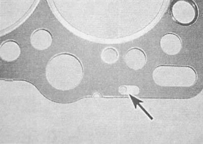
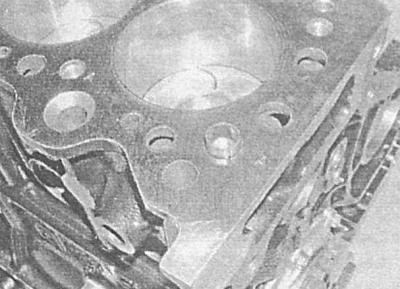
6. On these engines, the gap between the head and the pistons is controlled by the thickness of the gasket. In the left front corner of the gasket, notches are provided, by the number of which it is possible to determine its thickness.
A - Identification of the thickness of the gasket of the cylinder head of the 1.7 l SOHC engine (one notch)
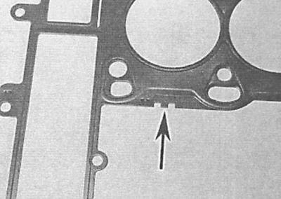
B - Identification of the thickness of the gasket of the cylinder head of the 1.7 l DOHC engine (one notch)
C - Identification of the thickness of the sealing gasket of the cylinder head of the 2.0 l engine (two notches)
A.
B.
C.
| Number of notches | Gasket thickness, mm | ||
| Engines 1.7 l SOHC | Engines 1.7 L DOHC | Engines 2.0 l | |
|
No notches |
1.30 |
1.45 |
1.20 |
|
One notch |
1.40 |
1.50 |
1.30 |
|
Two notches |
1.50 |
1.55 |
1.40 |
7. The required gasket thickness can also be calculated from the amount of piston protrusion above the block surface (see below).
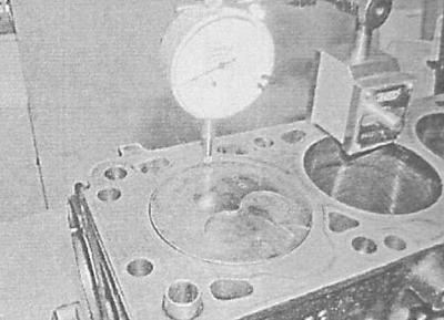
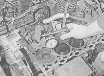
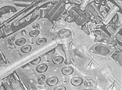
8. Bring the engine to the TDC position of the end of the compression stroke of the piston of the first cylinder. Install a plunger-type dial gauge on the block, press the plunger of the gauge against the mating surface of the block, and zero the instrument. Now move the plunger to the surface of the piston bottom of the first cylinder and measure the amount of protrusion (on 1.7L SOHC engines - at three points on the bottom of each piston). Further, acting in a similar manner, determine the amount of protrusion of the piston of the fourth cylinder.
A - Measuring piston protrusion on 1.7L SOHC engines
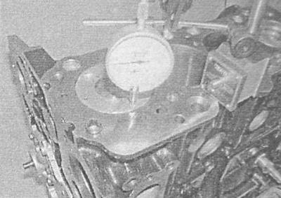
B - Measurement of piston protrusion on 1.7L DOHC engines
C - Measurement of piston protrusion on 2.0L engines
A.
B.
C.
9. Turn the crankshaft half a turn to bring the pistons of the 3rd and 2nd cylinders to the TDC positions and repeat the measurements. Finally, return the engine to the TDC position of the piston of the first cylinder.
10. On 1.7L SOHC engines add up all 12 results (three for each piston) and divide the result by 12; on engines 1.7 l DOHC and 2.0 l the gasket is selected according to the maximum protrusion. Using the table below, calculate the required thickness of the new gasket.
| Piston protrusion, mm | Required gasket | ||
| Engines 1.7 l SOHC | Engines 1.7 L DOHC | Engines 2.0 l | |
|
less than 0.80 |
0.63—0.696 |
0.40—0.50 |
without notches |
|
0.80—0.90 |
0.697—0.763 |
0.51—0.60 |
one notch |
|
0.90 or more |
0.764—0.830 |
0.61—0.70 |
two notches |
On 1.7L SOHC engines, if any of the pistons protrudes more than 0.05 mm more than the others, install a thicker gasket. For example, if the average protrusion is 0.79 mm and one of the measurements is 0.85 mm (0.06mm difference), use a gasket with a single notch.
Installation
Replacing the cylinder head bolts is mandatory, regardless of their current condition!
Engines 1.7 l SOHC
1. Wipe dry the mating surfaces of the block and head with a clean rag.
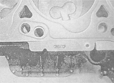
2. Make sure the two guide bushings are in place. Lay a new sealing gasket on the mating surface of the cylinder block, - the gasket is placed with a mark «OBEN/TOP» up and down the engine.
3. Turn the crankshaft counterclockwise 90°to prevent contact between pistons and valves.
4. With the help of an assistant, carefully install the head on the cylinder block - make sure that the guide bushings fit into the mating sockets.
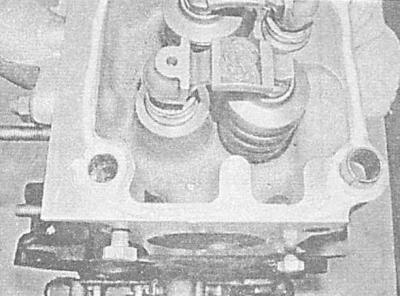
5. Lubricate the hydraulic lifters, locking washers and valve levers with clean engine oil and install the components in their regular places. Lubricate the friction surfaces of the valve actuator levers with a molybdenum-containing grease of type «Molikot A».
6. Apply a layer of suitable sealant (consult a service station) on the upper mating surface of the cylinder head.
7. Carefully install the timing case (with embedded camshaft) on the cylinder head.
8. Lubricate the threaded part and the underside of the bolt heads with clean engine oil with a thin layer of oil, then screw in the bolts and tighten them by hand.
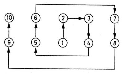
9. Working in a strictly defined sequence, in several stages evenly, tighten the head bolts with the force of the 1st stage.

10. In the same order, tighten the bolts to the corners, first the 2nd, then the 3rd and 4th stages, use the goniometer nozzle, or apply reference marks with paint or a marker.
11. Install the thermostat housing on the right side of the cylinder head using new O-rings on the ends of the coolant path tube at the rear of the cylinder block and between the thermostat housing and cylinder head. Make sure the metal tube at the rear of the cylinder block is aligned with the body. Tighten the fixing bolts to the required torque.
12. Install the oil supply pipe to the cylinder block and turbocharger, tightening the union bolts to the required force.
13. Install the support bracket on the generator and turbocharger, - make sure that the fasteners are tightened with the required force.
14. Apply sealant to the mating surface of the exhaust pipe of the exhaust system and the gasket and install them on the exhaust manifold. Tighten the nuts to the required torque.
15. Attach the support bracket to the exhaust manifold and block and tighten its mounting bolts to the required torque.
16. Attach the turbocharger oil return pipe to the top of the oil pan - do not forget to replace the sealing washers.
17. Install the rear timing belt cover, powertrain mount bracket, idler pulley, camshaft sprocket and timing belt (see Removal and installation of the belt tensioner and timing gears (engines 1.7 l) and Removing and installing timing belt).
18. Install the right powertrain mount and the lower and upper sections of the timing belt cover (see Removing and installing timing cover).
19. Install the crankshaft pulley (see Removal and installation of the crankshaft pulley). Install the front wheel and lower the vehicle to the ground.
20. Connect the electrical wiring to the glow plugs. Tighten the nuts securely.
21. Install the hoses of the cooling path to the outlet pipe and fix the latter on the cover of the gas distribution mechanism housing.
22. Connect the injection pump fuel lines to the timing case.
23. Connect a hose of a cooling path to the thermostat case and the top branch pipe of a radiator. Tighten the mounting clamps securely.
24. Connect the electrical wiring to the thermostat housing.
25. Connect the wiring connectors to the temperature sensor, boost pressure sensor and EGR solenoid valve.
26. Connect the crankcase ventilation hoses to the cover of the gas distribution mechanism housing, securely tighten the mounting clamps.
27. Connect the vacuum hose and brake booster servo tube to the vacuum pump.
28. Connecting the air hose connecting the turbocharger to the intercooler - make sure that the pipe is securely fixed with mounting clamps.
29. Establish the generator on an adjusting lath and tighten the bottom bolt of fastening of the generator with the demanded effort.
30. Install accessory drive belts (see chapter Current service).
31. Install the air cleaner housing with air ducts and MAF sensor (see chapter Power and exhaust systems).
32. Fill the cooling system (see chapter Cooling, heating systems).
33. Check the engine oil level and correct if necessary.
34. Torque tighten the wheel bolts.
35. Install and connect the battery.
36. Start the engine and check it for signs of leak development. Warming up the engine to normal operating temperature, tighten the cylinder head bolts to the angle of the 5th stage of tightening (see Specifications).
Engines 1.7 L DOHC
1. Wipe dry the mating surfaces of the block and head with a clean rag.
2. Make sure the guide bushings are in place.
3. Turn the crankshaft counterclockwise 60°from TDC to prevent valve contact with the pistons.
4. With the help of an assistant, install the head on the block - make sure that the guide bushings get into the mating sockets.
5. Lubricate the threaded part and the underside of the bolt heads with clean engine oil with a thin layer of oil, then screw in the bolts and tighten them by hand.
6. Working from the middle to the edges, in several stages evenly, tighten the head bolts with the force of the 1st stage.
7. In the same order, tighten the bolts to the corners, first the 2nd, then the 3rd, 4th and 5th stages, use the goniometer nozzle, or apply reference marks with paint or a marker.
8. Further installation is carried out in the reverse order to the dismantling of the components. Pay attention to the following points:
9. Turn the crankshaft in the normal direction before installing the timing belt (clockwise) until the TDC marks are aligned;
10. After installing the injectors and fuel pipes, check the power system for signs of leaks (see chapter Power and exhaust systems);
11. Make sure the wiring is correct;
12. Check the setting of valve clearances, if necessary, make appropriate adjustments (see Checking and adjusting valve clearances (1.7L DOHC engines));
13. Finally, fill the cooling system (see chapter Cooling, heating systems).
Engines 2.0 l
When installing, you will also need new bolts for fastening the upper chain guide and a bolt for fastening the camshaft sprocket.
1. Wipe dry the mating surfaces of the block and head with a clean rag.
2. Make sure the guide bushings are in place. Lay a new gasket on the mating surface of the block.
3. Make sure that the crankshaft is at TDC and locked, the valve drive cams of the first cylinder are turned with the working projections up, and the groove in the end surface of the shaft journal is turned parallel to the cut of the head (control hole at the top).
4. With the help of an assistant, install the head on the cylinder block - make sure that the guide bushings get into the reciprocal sockets. When installing the head, thread the timing chain into it and secure it to the surface of the head with a screwdriver or a suitable rod.
5. Lubricate the threaded part and the underside of the bolt heads with clean engine oil with a thin layer of oil, then screw in the bolts and tighten them by hand.
6. Working in a strictly defined sequence, in several stages evenly, tighten the head bolts with the force of the 1st stage.
7. In the same order, tighten the bolts to the corners, first the 2nd, then the 3rd, 4th, 5th and 6th stages, use a goniometer nozzle, or apply reference marks with paint or a marker.
8. Screw in bolts of fastening of a head to a cover of a gas-distributing chain and the block of cylinders and tighten them with the demanded effort.
9. Turn the generator to its normal position and tighten the upper bolt of its fastening with the required force (see chapter Engine electrical equipment).
10. Attach hoses of system of cooling to a head of cylinders and fix them collars.
11. Install the intake piping, exhaust manifold and related components (see chapter Power and exhaust systems).
12. Install the camshaft sprocket (see Removing and installing timing chains and sprockets, checking the condition of components (engines 2.0 l).
13. Install new sealing washers on the nipple connectors of the injection pump fuel lines. Tighten the connectors to the required torque (see chapter Power and exhaust systems).
14. Finally, fill the cooling system (see chapter Cooling, heating systems).
Visitor comments