
Removing
Engines 1.7 l SOHC
The use of a special tool KM-890 when removing the camshaft from the 1.7 l SOHC engine ensures that the cylinder head gasket is not disturbed. If there is no tool at hand, you will have to remove the cylinder head (see Removing and installing cylinder head).
1. Remove the battery.
2. Remove the camshaft gear (see Removal and installation of the belt tensioner and timing gears (engines 1.7 l). Rotate the crankshaft 90°counterclockwise to prevent the pistons from contacting the valves.
3. Release the clamps and remove the air duct connecting the turbocharger to the intercooler. Also remove the sleeve from the intercooler to the intake manifold.
Both sleeves are also fixed in intermediate clamps (see the Head of the Power supply and release system).
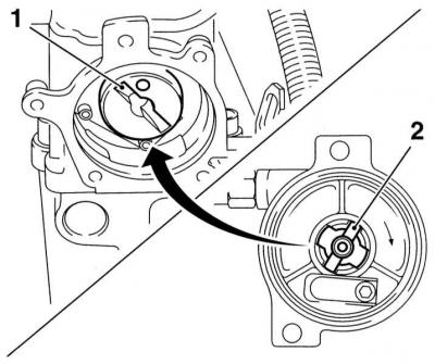
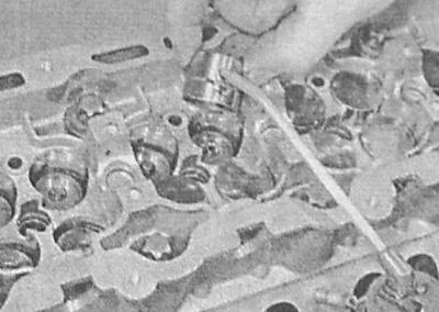
4. Disconnect from the vacuum pump (4) brake booster servo tube and vacuum tube (2—3).
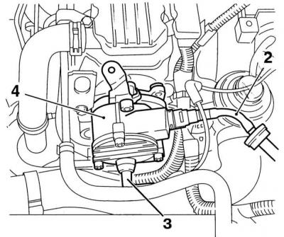
5. Turn out fixing bolts and remove the pump together with an arm of an air duct of system of a turbocharging.
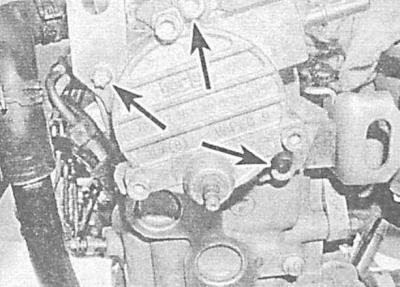
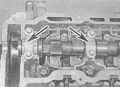
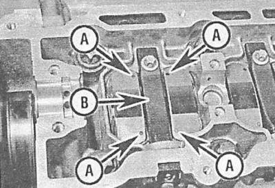
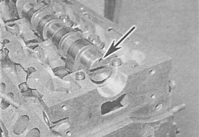
6. Remove the two cap screws (Allen) and remove the camshaft thrust plate.
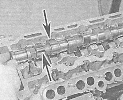
7. If you have the KM-890 tool on hand, use it. The device consists of a set of plates with adjustable legs. The plates are attracted to the gas distribution mechanism housing, squeezing the valve drive levers with their legs, after which the camshaft can be freely removed from the drive mechanism housing. If there is no possibility of using the device, you will have to remove the gas distribution mechanism housing. Since the body bolts also attach the cylinder head at the same time, it will also have to be removed (see Removal and installation of a head of cylinders).
Bolts and gasket are not reusable and must be replaced with new ones during assembly, regardless of their condition.
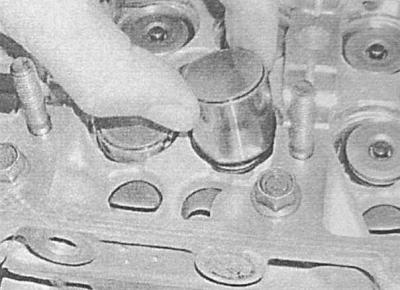
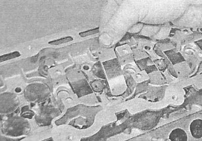
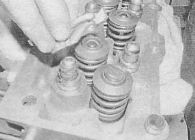
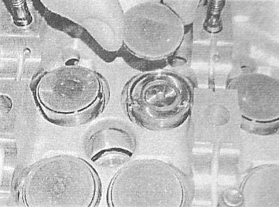
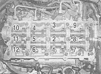
8. After removing the camshaft, prepare 8 transparent plastic bags or small plastic cups and label them according to the numbering of the valves. Remove the levers of the valve drive, fixing their figured washers and the hydraulic racks of the compensators. Arrange the removed components in bags / cups in accordance with the markings.
Engines 1.7 L DOHC
1. Remove the timing cover (see Removal and installation of a cover of the gas-distributing mechanism).
2. Remove fuel injectors (see chapter Power and exhaust systems).
3. Remove the camshaft gear (see Removal and installation of the belt tensioner and timing gears (engines 1.7 l)).
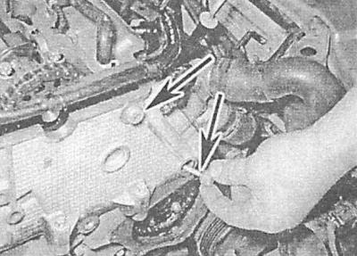
4. Turn out fixing nuts and remove a cover of the 5th support of camshafts from the left (transmission side) sides.
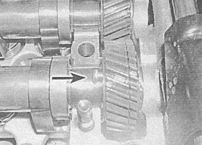
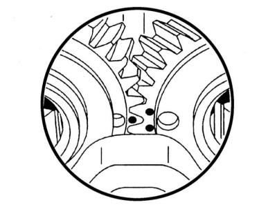
5. The exhaust camshaft drive gear is equipped with an additional gear section to compensate for end play. The compensation section should be interlocked with the main gear of the shaft using a suitable bolt or rod. Insert the bolt/rod through the hole on the inside of the main gear and push it through the compensation section. Such a lock will unload the compensation spring when removing any of the camshafts.
6. Moving in a spiral from the edges to the middle, gradually, one turn per approach, loosen the nuts securing the covers of the remaining supports to relieve stress from the valve springs gradually and evenly. After all valve springs are unloaded, the nuts can be unscrewed by hand.
Unscrewing the nuts in random order is fraught with the destruction of the camshaft support bearing caps, and you will have to change the entire cylinder head, since it is cast and machined together with the support caps, and covers are not individually supplied to the market.
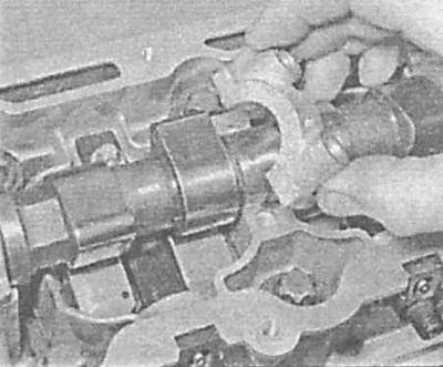
7. Remove the support covers - try to remember the installation position of the components.
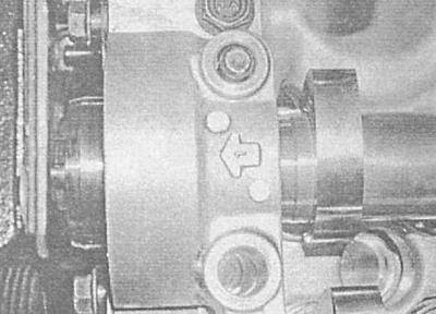
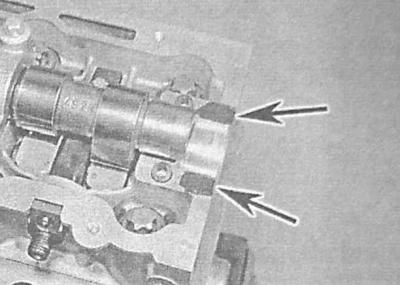
Serial numbers are marked on the supports (1 to 5). The marking in the form of an arrow when installing the covers must point towards the timing belt.
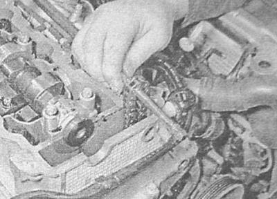
8. Remove camshafts from a head of cylinders.
9. Prepare 16 small clear plastic bags or clean plastic cups and label them according to the valve numbers. Remove the pushers with washers from the head and arrange them in the appropriate cups.
Engines 2.0 l
When installing, you will need a new camshaft sprocket bolt and new upper chain guide bolts.
1. Disconnect the negative cable from the battery and remove the timing cover (see Removal and installation of a cover of the gas-distributing mechanism).
2. Remove the brake booster servo vacuum pump (see chapter Brake system).
3. Bring the piston of the 1st cylinder to the TDC position of the end of the compression stroke (see Bringing the piston of the first cylinder to the position of the top dead center of the end of the compression stroke (TDC)) and lock the crankshaft in this position.
4. In order to provide free access to the injection pump sprocket cover, remove the air cleaner housing and the exhaust pipe of the exhaust system (see chapter Power and exhaust systems). Also remove the accessory drive belt (see chapter Current service). Mark the position of the right powertrain mount in relation to the cylinder head bracket. Turn out three bolts of fastening of a support to an arm of a head of cylinders and three bolts of fastening of its mudguard. Support the right side of the engine with a trolley jack, raising it as high as possible without excessively loading other supports and communication lines (hoses, cables, wiring harnesses).
5. Remove the top chain tensioner (see Removal and installation of timing chain tensioners (engines 2.0 l)).
6. Turn out the bottom bolt of fastening of a rack of a tension roller of a belt of a drive of auxiliary units, give a bolt of an axis of the basis of a tensioner and remove assembly of the last from the engine.
You should not unnecessarily remove the rack from the tensioner assembly - it will have to be ground during installation.
7. Turn out fixing bolts and remove a cover of asterisks of TNVD from a cover of a drive of GRM.
8. Mark the position on your top chain sprockets. Also mark the position of the camshaft sprocket on the latter trunnion.
9. Turn out fixing bolts and take the damper of the top chain from a head of cylinders.
Before releasing the bolts, they should be heated with a heat gun (powerful hair dryer) in order to soften the sealant applied to the thread.
10. Holding the camshaft with an open-end wrench, unscrew the sprocket mounting bolt, - before releasing the bolt, remove the camshaft fixing device, - do not forget to install the device in place after the bolt is unscrewed.
11. Release the camshaft sprocket from the chain and remove it from the engine.
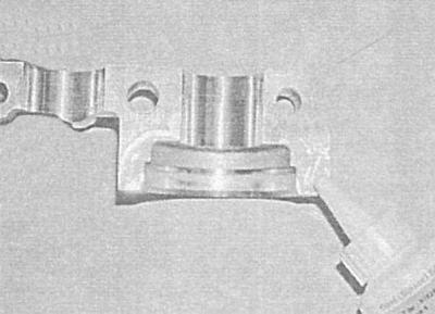
12. Fix the chain with a screwdriver to prevent it from falling into the head - lay the screwdriver on the mating surface of the head.
13. Pay attention to the marking of the camshaft bearing caps. The covers are numbered in order from 1 to 5, with cover No. 1 located on the side of the timing chain. If the markings are hard to see, apply a new one yourself to avoid assembly confusion.
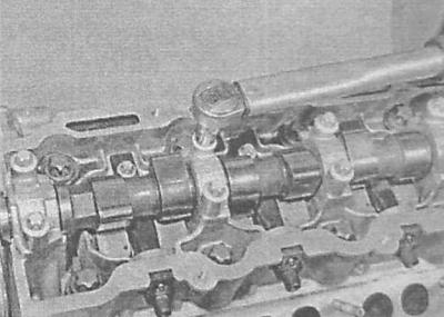
14. Moving in a spiral from the edges to the middle, gradually, one turn per approach, loosen the cap bolts - after all valve springs are unloaded, the bolts can be unscrewed manually. Fold the removed bolts together with their covers - try not to lose the guide bushings installed in the 5th support. Remove the camshaft from the cylinder head.
Unscrewing the nuts in random order is fraught with the destruction of the camshaft support bearing caps, and you will have to change the entire cylinder head, since it is cast and machined together with the support caps, and covers are not individually supplied to the market.
15. Prepare eight clear plastic bags or small plastic cups and label them according to the valve numbers. Remove the valve actuating levers and arrange them in bags / cups in accordance with the applied marking.
16. If it is necessary to remove the hydraulic pushers, dismantle the adapter tubes of the injectors (see chapter Power and exhaust systems). Removing the pushers is best done with a magnetized rod or rubber grip. Arrange the removed components in bags / cups in accordance with the marking.
Examination
1. Carefully examine the condition of the bearing journals and camshaft cams. Replace shaft if scored or scratched. Also check the condition of the working surfaces of the plain bearings in the bearings of the gas distribution mechanism housing. On 1.7L SOHC engines damaged and worn bearings can be replaced. On engines 1.7 l DOHC and 2.0 l the entire cylinder head assembly has to be replaced, since it is cast and machined together with the bearing caps, and caps are not marketed individually.
2. Laying the camshaft (s) into a prism, determine the value of its radial runout (on bearing journals) using a plunger-type dial gauge. When the measurement results are out of range (see Specifications) the camshaft must be replaced.
3. On engines 1.7 l The camshaft seal must also be replaced (see Camshaft oil seal replacement (engines 1.7 l)).
4. On engines 1.7 l SOHC and 2.0 l evaluate the degree of wear and the general condition of the working surfaces of the valve drive levers in contact with the camshaft cams. In case of detection of cracks, cavities, furrows and scuffs, the levers should be replaced.
5. On 1.7L SOHC models check the condition of the camshaft thrust plate, replace if necessary.
With increased axial play of the shaft, the plate must also be replaced.
6. Check up a condition of pushers/hydraulic compensators and their landing sockets in a head. If there are signs of excessive wear of the working surfaces, cracks, scoring and other damage, replace the pushers.
The pushers must also be replaced if the operation of the valve mechanism has recently been accompanied by an increased background noise.
Installation
Engines 1.7 l SOHC
1. Lubricate all hydraulic pushers, fixing washers and valve drive levers with clean engine oil and install them strictly in their original places. Lubricate the friction surfaces of the levers with a molybdenum-containing grease of the type «Molikot A».
2. Install the KM-890 tool, carefully insert the camshaft into the timing housing, threading its trunnion through a new oil seal and secure it with a thrust plate. Tighten the thrust plate mounting bolts to the required torque.

3. Make sure that the valve actuator levers and their fixing washers are in place and not warped, then carefully remove the KM-890 tool.
4. Install the camshaft gear while hand-tightening its fastening bolt.
5. Turn the camshaft so that the cam of the exhaust valve drive of the 1st cylinder (close to timing belt) turned with the working ledge up. Rotate the crankshaft 90°to TDC position and install the timing belt (see Removing and installing timing belt).
6. Fill the vacuum pump shaft into the hole in the left end of the gas distribution mechanism housing and fix the turbocharger tube bracket with the upper pump mounting bolt. Make sure that the vacuum pump drive shaft is properly engaged with the camshaft stub. Tighten the pump mounting bolts to the required torque.
7. Connect the brake booster servo vacuum hose to the vacuum pump.
8. Reinstall the hose connecting the intercooler to the intake piping, as well as the air duct that runs between the compressor and the intercooler. Install the mounting clips and securely tighten the bracket mounting bolts.
9. Install and connect the battery.
Engines 1.7 L DOHC
1. Lubricate the pushers with clean engine oil and install strictly in their original places - make sure that all the washers are installed correctly.
2. To prevent the risk of the valves coming into contact with the piston crowns, turn the crankshaft approximately 60°counterclockwise. Lubricate the pushrod washers and camshaft bearings with clean engine oil and place the shafts on the bearings. Make sure the compensation section of the exhaust camshaft gear is interlocked with the main gear. Make sure that the mark on the outer surface of the exhaust camshaft gear is between the two marks on the outer surface of the intake camshaft gear and approximately in line with the cut of the timing case.
If the exhaust camshaft has been replaced, you will need to purchase a Vauxhall KM-6092 tool to compress the balance gear spring prior to installation.
3. Make sure that the mating surfaces of the bearings and camshaft covers are absolutely clean and dry. Lubricate mating surfaces and camshaft lobes with clean engine oil.
4. Lubricate the mating surfaces of the first support and its cover with a suitable sealant (consult a service station).
5. Install the support covers from No. 1 to No. 4 in their places - the covers are marked and must be installed with arrows in the direction of the timing belt.
6. Screw on the nuts for fastening the covers, tightening them only by hand so far.
7. Remove the bolt/rod securing the exhaust camshaft gear section, then install the 5th support cover.
8. Acting in a strictly defined sequence, gradually, one turn per approach, tighten the cap nuts, smoothly loading the valve springs. Continue tightening in the same sequence until the covers are pressed against the supports, then tighten all fasteners to the required torque.
Randomly tightening the nuts will destroy the camshaft bearing caps, and you will have to change the entire cylinder head, since it is cast and machined with the bearing caps, and caps are not individually supplied to the market.
9. Install a new camshaft oil seal (see Camshaft oil seal replacement (engines 1.7 l)).
10. Install the camshaft sprocket and timing belt (see Removal and installation of the belt tensioner and timing gears (engines 1.7 l) and Removing and installing timing belt).
11. Check the clearances in the valves, if necessary, adjust them (see Checking and adjusting valve clearances (1.7L DOHC engines)), then install the timing cover (see Removal and installation of a cover of the gas-distributing mechanism).
12. Replace the nozzles (see chapter Power and exhaust systems).
Engines 2.0 l
1. If removed, lubricate the tappets with clean engine oil and install them in their original places in the cylinder head. Install the injector adapter tubes (see chapter Power and exhaust systems).
2. Reinstall the valve levers (marks on their upper surface to the injector adapter tubes).
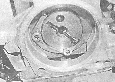
3. Lubricate the cams and bearing journals of the camshaft with clean engine oil and lay the shaft in its original place. Make sure that the crankshaft is still locked in the TDC position and turn the camshaft with the cams of the first cylinder valve drive cams up so that the groove in the end of the camshaft trunnion is parallel to the upper cut of the head, and the valve timing control hole is in position «at 12 o'clock».
4. Make sure that the mating surfaces of the camshaft bearings and their covers are absolutely clean and dry. Lubricate the cams and camshaft journals with clean engine oil.
5. Lubricate the mating surfaces of the 5th (extreme left) shaft supports, then install the guide bushings into the cylinder head.
6. Reinstall the camshaft bearing caps. The covers are numbered in order from 1 to 5 and when viewed from the front of the engine, the numbers should read correctly.
7. Tighten the cap bolts by hand, then, moving in a spiral from the middle to the edges, gradually, one turn per approach, tighten the bolts of all caps, smoothly loading the valve springs. Continue to tighten the fasteners until the covers are pressed against the supports, and finally tighten the bolts to the required torque.
Randomly tightening the nuts will destroy the camshaft bearing caps, and you will have to change the entire cylinder head, since it is cast and machined with the bearing caps, and caps are not individually supplied to the market.
8. Following the correct alignment of the marks applied during the dismantling process, put the chain behind the sprockets of the high-pressure fuel pump and the camshaft. Place the camshaft sprocket on the last axle (also make sure that the labels are correctly aligned). Install and tighten the NEW mounting bolt.
9. Replace the upper chain guide (mounting lug up), install the NEW mounting bolts and tighten them to the correct torque.
10. If you have special fixing devices at hand, adjust the valve timing (see Checking and adjusting the valve timing (engines 2.0 l)). When finished adjusting, remove the fixtures.
11. If it is not possible to use special devices, achieve alignment of the landing marks of the sprocket and camshaft applied during dismantling. Holding the flats of the camshaft with an open-end wrench, tighten the sprocket mounting bolt to 1st stage torque. Make sure that the marks are correctly aligned, tighten the bolt successively at the corners of stages 2 and 3 of tightening - use a goniometer nozzle, or apply reference marks with paint or a marker.
12. Install the top chain tensioner (see Removal and installation of timing chain tensioners (engines 2.0 l)).
13. Make sure that the mating surfaces of the injection pump sprocket covers and the timing drive are absolutely clean and dry. If the cover has been seated on a gasket, be sure to replace the latter. Screw fixing bolts and tighten them with the required effort. If a gasket was not provided, fill the cover groove with a pad of sealant about 2 mm thick, then press the cover, screw in the mounting bolts and tighten them to the required torque.
14. Install the accessory drive belt tensioner by tightening the mounting and axle bolts to the required torque. When replacing the tensioner, or after disassembling it, it is necessary to grind the rack in - use the socket head, putting it on the hexagonal part of the base. If the rack functions normally, install the accessory drive belt (see chapter Current service).
15. Establish on a head of cylinders assembly of the right support of a suspension bracket of the power unit. Lower the unit, then fix the support on the mudguard, making sure that the landing marks made during the dismantling process are aligned correctly. Tighten the fixing bolts to the required torque.
16. Install the timing cover (see Removal and installation of a cover of the gas-distributing mechanism).
17. Install the exhaust pipe, air cleaner housing and crankshaft position sensor (see chapter Power and exhaust systems).
18. Install the vacuum pump assembly (see chapter Brake system).
Visitor comments