


Removal
Engines 1.7L SOHC
1. Remove the rear timing belt cover (see Removal and installation the timing belt cover).
2. Remove the oil pan casting section (see Removal and installation the oil pan).
3. Remove the tensioner assembly and idler roller (see Removal and installation timing chain tensioners (2.0L engines).
4. On models with a manual transmission, ask an assistant to engage the highest gear and fully depress the foot brake pedal to prevent the crankshaft from turning. On models with automatic transmission, unscrew one of the torque converter mounting bolts and tighten it to the transmission housing using a steel bar and suitable bolts with washers (see Chapter Automatic transmission). If the engine is removed from the vehicle, the flywheel/drive plate must be locked (see Removal, checking condition and installing flywheel/drive disk). Unscrew the mounting bolt and remove the gear wheel.
5. Disconnect the oil pipe from the oil filter housing and move the pipes together with the bracket to the side.
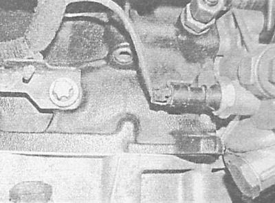
6. Disconnect the electrical wiring from the oil pressure sensor.
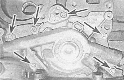
7. Remove the six mounting bolts and remove the oil pump from the guide bushings.
8. Using a screwdriver, remove the seal from the pump body and discard it. The seal must be replaced during assembly.
Engines 1.7L DOHC
The oil pressure reducing valve is screwed into the cylinder block and cannot be removed without first dismantling the high-pressure fuel pump.
1. Remove the timing belt (see Removal and installation the timing belt).
2. Remove the oil pump and crankshaft gears (see Removal and installation the timing belt tensioner and timing gears (1.7L engines).
3. Remove the cast section of the oil pan (see Removal and installation the oil pan). Unscrew the mounting bolts, slide the oil pump cover toward the crankshaft journal, taking precautions not to drop the guide bushings. Remove the sealing ring installed around the body of the oil pump and discard it - the ring must be replaced during assembly.
4. Use a marker to mark the position of the outer rotor of the pump. During assembly, the components must be installed exactly in the same position.
5. Remove the inner and outer rotors from the cylinder block.
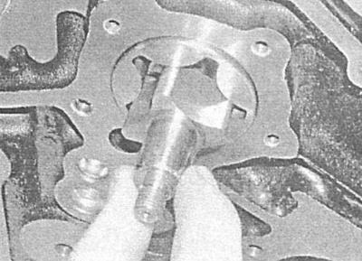
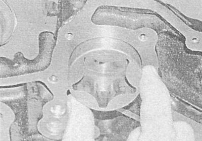
6. If necessary, remove the fuel injection pump (see Chapter Power and exhaust systems) and unscrew the pressure reducing valve from the rear of the cylinder block. The valve is located to the right of the lower fuel injection pump mounting bracket. Remove the sealing ring.
2.0L Engines
The oil pump is built into the timing belt cover, for a description of the procedures for its removal and installation, see. Removal and installation the timing belt cover.
The oil pump pressure relief valve can be removed without dismantling the timing cover. To dismantle the valve, simply remove the oil pan.
Examination
Engines 1.7L SOHC
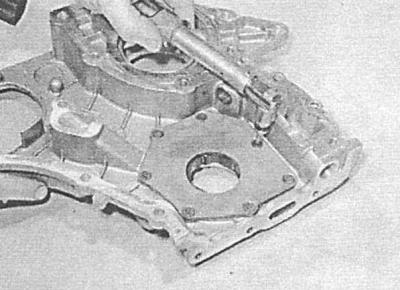
1. With the pump removed from the engine, remove the Phillips head screws and remove the inner pump cover.
2. Check the clearances between the teeth of the outer and inner rotors, as well as between the outer rotor and the pump body (outer rotor radial clearance).
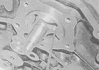
3. Using a steel ruler and a blade-type feeler gauge, measure the axial clearance (play) of the rotors.
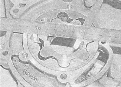
4. If the measurement results are outside the permissible ranges (see Specifications), replace the corresponding components. Note that the surface of the outer rotor has a mounting mark.
5. The pressure reducing valve can be removed from the pump body for cleaning and checking the condition of the components.
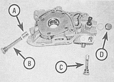
A - Pressure reducing valve piston
B — Spring of the pressure reducing valve assembly
C - Thermostatic valve
D — Plug
6. The oil pressure sensor is screwed into the rear of the pump. A faulty sensor must be replaced (see Chapter Engine electrical equipment).
Material copied from this resource (OpelBook.ru)
7. The oil cooler thermostatic valve/filter bypass valve is screwed into the oil filter housing.
Engines 1.7L DOHC
1. Thoroughly clean all components and carefully examine the condition of the rotors, housing and pump cover. If damage or signs of excessive wear are detected, replace the defective components. If the pump housing in the cylinder block is marked, consult an authorized Opel service station.
2. If the condition of the components is found to be satisfactory, install the rotors into the pump assembly housing. Using blade-type feeler gauges, measure the clearances between the outer rotor and the pump housing and the clearance between the teeth of the inner and outer rotor. Measure the axial play of the rotors and check the flatness of the cover. If the measurement results are outside the permissible ranges (see Specifications), replace worn components.
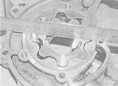
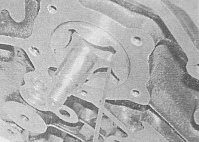
3. If the pressure reducing valve was removed, check the freedom of movement of the piston and the smoothness of its return under the influence of the force developed by the spring. If necessary, replace the valve assembly.
2.0L Engines
1. Loosen the mounting bolts and remove the pump cover from the inside of the chain cover.
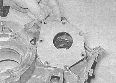
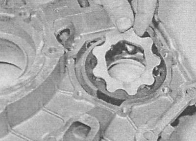
2. Use a marker to mark the installation positions of both rotors.
3. Remove the rotors from the pump body.
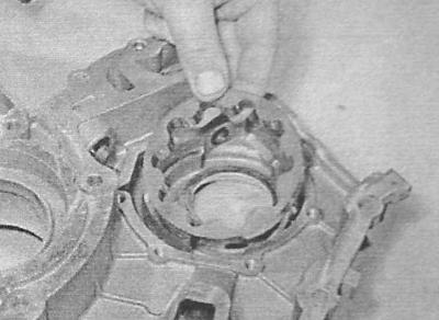
4. Unscrew the plug of the oil pressure regulation valve at the base of the pump housing.
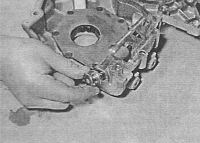
5. Remove the spring, bushing and plunger - try to remember the installation position of the components. Remove the sealing ring from the valve plug.
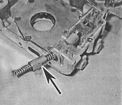
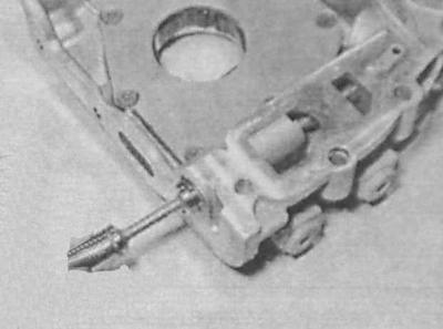
6. Remove the pressure relief valve plug from the rear of the chain cover - the valve is mounted above the three bolts at the rear of the cover.
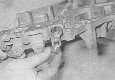
7. Remove the spring and plunger from the cover - try to remember the installation position of the components. Remove the sealing ring from the plug.
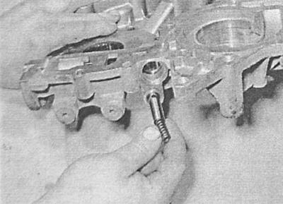
8. Clean all components. Assess the wear of the rotors, pump body and valve plungers. Replace defective components. If the pump rotors are already marked, replace the entire pump assembly.
9. If the condition of all components is not in doubt, reassemble them in reverse order, paying attention to the following points:
10. Ensure that the rotors and plungers are correctly oriented when installed in the pump assembly;
11. Do not forget to replace the sealing rings of the plugs, make sure that the plugs are tightened with the required force;
12. Make sure that the pump cover mounting bolts are also tightened to the required torque;
13. Finally, fill the oil pump with clean engine oil by manually turning the inner rotor.
Installation
Engines 1.7L SOHC
1. If removed, install a new relief valve O-ring and install the valve assembly into the cylinder block, tightening it to the required torque.
2. Using a cylindrical mandrel (a replacement socket head of the appropriate size, or a section of pipe of the appropriate diameter) or put a new seal into the oil pump housing (with sealing lips inward), — make sure that the mandrel rests only on the rigid outer edge of the seal. Make sure that the seal is pressed flush with the surface of the housing.
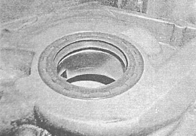
Before installation, lubricate the sealing lips of the oil seal with clean engine oil.
3. Lubricate the pump rotors with clean engine oil and seat them in the pump housing. Make sure that the alignment marks made during dismantling are correctly aligned. The markings should face the inside of the engine.
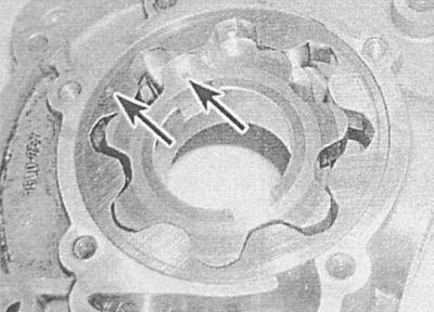
4. Apply a bead of suitable sealant to the inner mating surface of the pump housing inner cover and install it onto the housing.
5. Screw in the cover mounting screws and tighten them to the required torque.
6. Carefully wipe the mating surfaces of the pump body and the block. Check that the pump guide bushings are in place. Remove all traces of sealant from the threaded portion of the pump mounting bolts.
7. Replace the gasket and install the pump on the cylinder block, being careful not to damage the working edges of the oil seal on the crankshaft. Ensure that the cutouts in the inner rotor are correctly engaged with the corresponding projections on the crankshaft journal. Tighten the mounting bolts to the required torque.
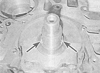
8. Further installation is carried out in the reverse order of dismantling the components. Please note the following points:
9. Tighten all fasteners to the required torque;
10. When installing the oil cooler oil pipe, do not forget to replace the sealing elements;
11. Check the engine oil level and make adjustments if necessary (see Chapter Routine maintenance);
12. Do not forget to replace the crankshaft timing gear mounting bolt.
Engines 1.7L DOHC
1. If the pressure relief valve was removed, replace the sealing ring and install the valve assembly into the cylinder block, tightening it to the required torque.
2. Lubricate the pump rotors with clean engine oil and install them into the pump body using the pre-applied markings.
3. Carefully pry the oil pump and crankshaft seals with a screwdriver before installing. Install the new oil seals with the jaws inside the engine and press them flush with the body using a suitable cylindrical mandrel (see above Engines 1.7L SOHC, p.2).
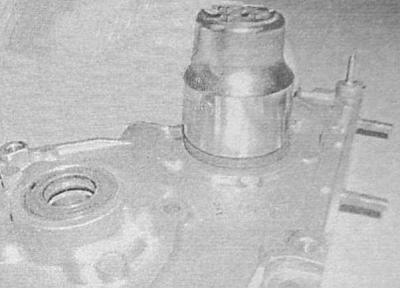
4. Make sure that the mating surfaces of the oil pump and cylinder block are absolutely clean and dry. Check that the guide bushings are in place. Remove all traces of sealant from the threaded parts of the pump mounting bolts.
5. Place the new seal into the groove around the pump body in the cover and apply a bead of suitable sealant to the mating surface of the pump cover.
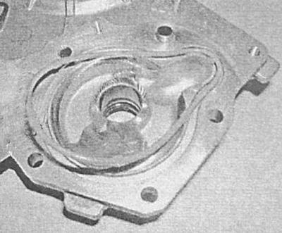
6. Carefully install the pump cover in place, being careful not to damage the lips of the crankshaft and rotor shaft seals. Align the cover with the guide bushings and press it against the block, controlling the position of the seals.
7. Lubricate the threaded parts of the mounting bolts with a special sealant for fixing threaded connections. Screw in the bolts and tighten them to the required force. Note that the longest bolt should be screwed into the lower left hole in the cover.
8. Install the timing gears and belt (see Removal and installation the timing belt tensioner and timing gears (1.7L engines).
9. Install the oil pan (see Removal and installation the oil pan).
10. Finally, fill the engine with clean oil (see Chapter Routine maintenance).
2.0L Engines
Cm. Removal, maintenance and installation of the oil pump.
Visitor comments