
The 1.7L SOHC and 2.0L engines are equipped with hydraulic compensators.
Examination
The importance of correctly setting the clearances in the valve mechanism of any internal combustion engine cannot be overestimated, due to its impact on the efficiency of the engine.
The check must be carried out on a cold engine!
1. Apply the parking brake, then jack up the front of the vehicle and place it on jack stands. In order to secure to the crankshaft pulley, remove the right front wheel. If equipped, remove the crankcase protection of the car.
2. Remove the timing cover (see Removal and installation of a cover of the gas-distributing mechanism). Remove nozzles (see chapter Power and exhaust systems).
3. Turn the engine in the normal direction (clockwise when viewed from the right side of the engine) behind the crankshaft pulley bolt until the alignment mark on the latter pulley aligns with the pointer on the oil pump cover.
4. Continue to turn the shaft rotate the crankshaft in the same direction until the cams of the valve actuator of the 1st cylinder of the inlet camshaft and the valve of the 3rd cylinder of the exhaust shaft turn their heels to the pushers (valves closed). Now you can start running the test.
5. Draw a diagram on a piece of paper (grid) adjusting the valves by numbering the cells in accordance with the numbering of the valves. Fill in the resulting table by entering in the cells the nominal values of the clearances of each valve.
Note that the intake and exhaust valve clearances are the same.
6. Turning the shafts as required (see above), measure the gaps between the heels of the cams and the ends of the pushers with a blade-type feeler gauge. Record the measurement results in the appropriate cells of the table.
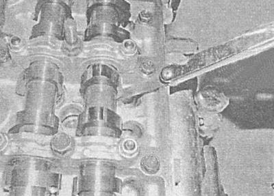
7. To check the gaps of the intake valve of the 3rd cylinder and the exhaust of the 4th, turn the crankshaft another half a turn (180°). Measure the gaps, write down the results.
8. In the same manner, turning the crankshaft 180°successively, measure the clearances of the exhaust valve of the 2nd cylinder and the intake of the 4th cylinder, then the exhaust of the 1st cylinder and the intake of the 2nd. Fill in all cells.
9. If the measurement results do not fall outside the allowable ranges (see Specifications), reinstall the timing cover (see Removal and installation of a cover of the gas-distributing mechanism).
10. Install nozzles (see chapter Power and exhaust systems).
11. Install the crankcase and wheel, then lower the vehicle to the ground and tighten the wheel bolts to specification.
12. If any clearances are incorrect, correct accordingly (see below).
Adjustment
1. Turn the crankshaft so that the drive cam of the valve to be adjusted is turned with the heel to the pusher.
Make sure the engine is not at the TDC position of the corresponding valve, as changing the shim will require compressing the valve spring, which can cause the valve to stop against the piston crown.
2. Turn the pusher with the slit in the top edge forward (exhaust pushers), or back (intake pushrods) by engine.
3. If special tool KM-6090 is not available, insert a large flat-blade screwdriver between the tappet edge and the camshaft base. Carefully, using a screwdriver as a lever, drown the pusher until it is possible to remove the adjusting washer. Removing the washer is easiest to do with a magnetized rod.
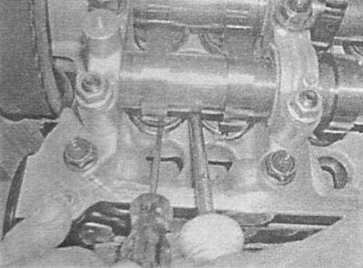
4. Wipe the washer and measure its thickness with a micrometer.
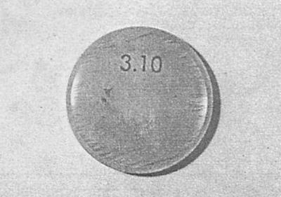
The washers have a marking, which, however, may be lost due to wear.
5. Add the valve clearance measurement to the result. To obtain the required thickness of the new washer, subtract the value of the nominal clearance value from the resulting amount, for example:
6. Valve clearance measurement result A = 0.35 mm
7. Thickness of the removed washer IN = 2.70 mm
8. Amount S = A B = 0.35 2.70 = 3.05 mm
9. Nominal gap WITH = 0.40 mm
10. New washer thickness D = S - C = 3.05 – 0.40 = 2.65 mm
It may be possible to produce the required by simply rearranging the washers from one pusher to another. Record and save for possible future adjustments to the thickness of all washers.
11. Prepare a washer of the required thickness, lubricate it with clean engine oil. Squeeze out the pusher and put the washer into it with the marking down.
12. In a similar manner, adjust the gaps of the remaining valves that need adjustment.
13. Turn the crankshaft several times to seat the washers on the pushers, then check the clearances before installing the timing cover. Install cover (see Removal and installation of a cover of the gas-distributing mechanism).
14. Install the crankcase and wheel, then lower the vehicle to the ground and tighten the wheel bolts to specification.
Visitor comments