
If the gap is too small, the valve timing changes, the compression process worsens, the engine power decreases, the engine becomes uneven. In extreme cases, valves can be deformed or burnt to the seats.
If the clearance is too large, mechanical noises appear, the valve timing changes, due to too short valve opening time and, consequently, poor filling of the cylinders, the engine power decreases, the engine runs unevenly.
Adjusting valve clearances can only be beneficial if the valves are well lapped, there are no unacceptable backlashes in their guides, and the ends of the valve stems are not clogged.
Valve clearances should be adjusted as part of maintenance, after repair, or when there is noise in the valve train.
Valve clearances should be checked and adjusted on a cold engine, i.e. when its temperature is equal to the ambient temperature.
Examination
1. Remove the cylinder head cover.
2. Set the piston of the first cylinder to the TDC position (see chapter Engines).
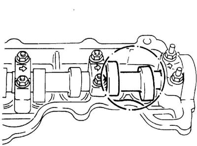
3. When the piston of the first cylinder is at TDC, the position of the camshaft cams is as shown (cams do not touch the valves of the first cylinder).
The position of the camshaft cams when the piston of the first cylinder is at TDC
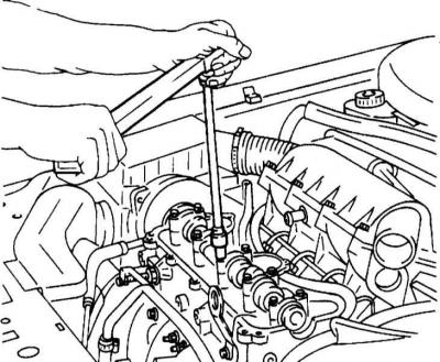
4. Before checking the valve clearances, check the tightness of the nuts securing the camshaft bearing caps. Tighten the nuts if necessary 25 Nm.
Check of effort of a tightening of nuts of fastening of covers of basic bearings
5. Insert a feeler gauge between the camshaft cam and the shim and check the clearance against the requirements of the Specifications in Chapter Vehicle settings and routine maintenance.
6. The probe should retract, as it were, otherwise the valve clearance needs to be adjusted.
7. Mark the position of the crankshaft pulley opposite the TDC mark. Turn the crankshaft half a turn in the direction of engine rotation. The next piston is now at TDC. According to the 1-3-4-2 ignition sequence, this is the third cylinder. Cylinder numbers are in order from one to four. Cylinder 1 is located at the toothed belt pulley. Check the gaps as described above. Then turn the crankshaft another half turn and check the valve clearance of cylinders 4 and 2.
8. If valve clearance adjustment is necessary, change the thickness of the feeler gauge until the true clearance value is obtained. Record the resulting value.
9. Establish a cover of a head of cylinders with a new lining and tighten bolts of its fastening with force 8 Nm.
Adjustment
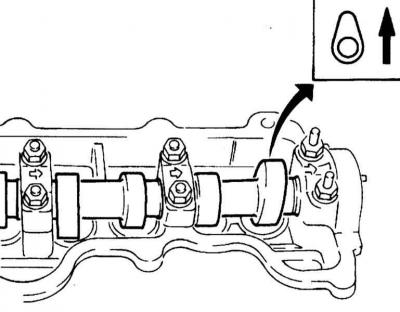
1. Rotate the crankshaft so that the top of the camshaft lobe above the adjustable valve faces up.
Setting the camshaft in position to adjust the valve clearance
2. Rotate the valve lifter so that the tappet groove faces forward.
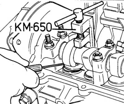
3. Valve clearance is adjusted by adjusting shims. To do this, press the pusher with a special tool OPEL-KM-650.
Pressing the pusher with a special tool
4. Take out an adjusting washer from a pusher and by means of a magnet.
5. Determine the thickness of the installed shim using a micrometer and record the measurement. The thickness of the washer should be engraved on its underside.
6. Calculate the thickness of the new shim using the formula N = T (A - S), where N is the thickness of the new shim, T is the thickness of the removed shim, A is the measured valve clearance, and S is the specification required (in Chapter Vehicle settings and routine maintenance) valve clearance value.
The shims can generally be used repeatedly until clearly visible wear marks appear. If the washer thickness marking is no longer visible, the washer should no longer be used.
7. Moisten a new adjustment in engine oil and install the washer with the marking down.
8. Adjust all valve clearances as described above.
9. Finally, check the valve clearances again.
Visitor comments