
2. Disconnect the gear shift lever from the gearbox (see chapter 6).
3. Disconnect the clutch control cable.
4. Disconnect the speedometer cable and the reverse light switch wiring from the gearbox.
5. Raise and support the front of the car so that you can later remove the engine and gearbox through the bottom (see paragraph 22).
6. Suspend the engine on hoists so as to remove the weight of the engine and gearbox from the mountings.
7. Disconnect the exhaust downpipe from the manifold and at the spring-loaded ball joint.
8. Mark the set position of the front left wheel on its hub, which is necessary in order not to upset the factory wheel balancing. You can simply paint one of the wheel bolts and the hole for it in the hub.
9. Remove the front left wheel.
Pic. 1.9. Connecting the clutch cable to the clutch release lever.
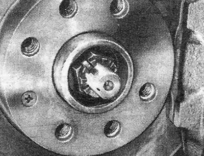
10. Remove the locknut or cotter pin from the castle hub nut and unscrew the nut. To prevent the hub from turning, screw the two bolts into place and pass the lever between them, thereby blocking the hub. Be careful not to damage the threads on the bolts.
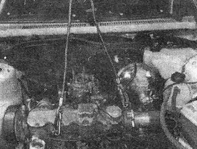
Pic. 1.10. Hang the engine on the hoists.
11. Disconnect the suspension control arm with the support (see chapter 10).
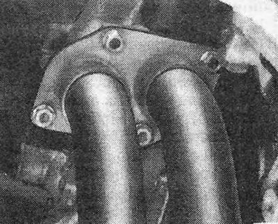
Pic. 1.11. Exhaust system connecting flange.
12. Check that the machine is securely supported and the suspension hangs freely.
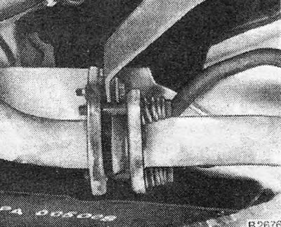
Pic. 1.12. Spring-loaded ball joint for exhaust system connection.
13. Remove the axle shaft from the hub. Usually this can be done by hand, but if the axle shaft does not move well, you can use a hammer with a plastic striker or a puller.
Pic. 1.13. Hub nut retainer.
14. Disconnect the left axle shaft from the transmission assembly (see chapter 7) and then, with the lower control arm facing outward, pull on the hub/stidle holder so that the axle shaft can be removed from the vehicle.
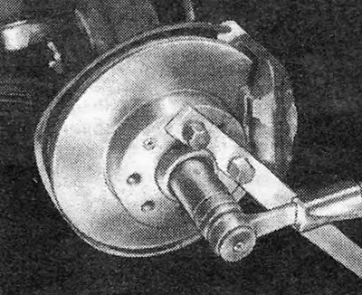
Pic. 1.14. Removing the hub nut.
15. Remove the bolt and disconnect the right rear engine support bracket from the mount.
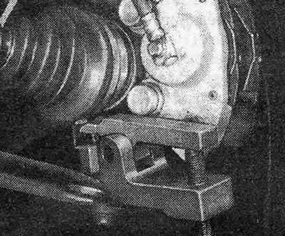
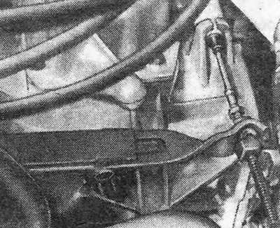
Pic. 1.15. Tie rod end ball joint remover.
16. Remove the bolt and disconnect the left rear engine support bracket from the mount.
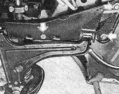
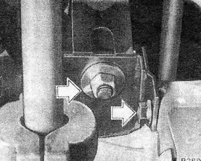
Pic. 1.16. Bolts securing the control arm support (shown by arrows) - 1.3 engines and some 1.6 engines.
17. Disconnect the grounding wires from the gearbox and engine housings (see photo).
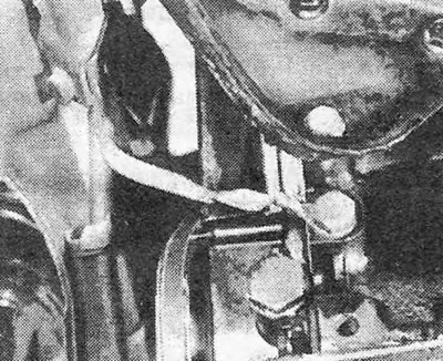
Photo 19.17. Grounding the engine to the lower part of the body.
Pic. 1.17. Right rear engine support bracket.
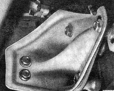
18. Remove the bolt and disconnect the right rear engine support bracket from the side member (see photo).
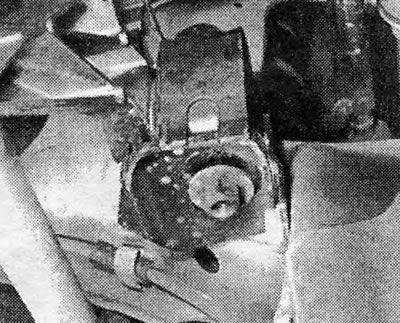
Photo 19.18. Right rear engine mount.
Pic. 1.18. Left rear engine mount nuts (shown by arrows).
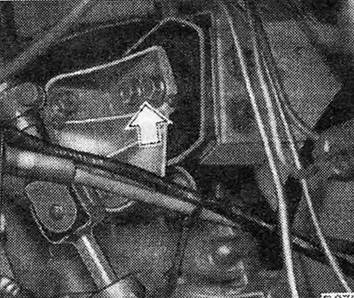
19. Remove the bolts and disconnect the front engine and gearbox mounts (see photos).
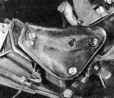
Photo 19.19A. Right front engine support bracket.
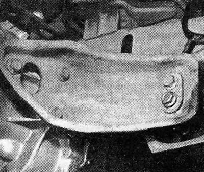
Photo 19.19В. Left front transmission support bracket.
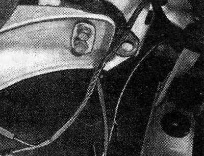
Pic. 1.19. Attaching the right rear engine support bracket to the body.
20. Check that the engine and gearbox hang freely on the hoists, and all wires, hoses, etc. were disconnected.
Pic. 1.20. Left front engine mount.
21. Carefully lower the engine and gearbox, simultaneously turning them so that the right axle shaft can be disconnected. When disconnecting the axle shaft, be careful not to drop it on the ground.
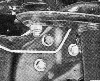
Pic. 1.21. Front engine mount nuts (shown by arrows).
22. Having lowered the engine with the gearbox to the floor, disconnect the hoist. You can use them to lift the front of the car to pull out the engine and gearbox. Alternatively, you can jack up the front end and install supports under the side members.
Visitor comments