
2. The pump takes oil from the sump through an oil intake tube with a strainer and supplies it under pressure through the oil filter and oil lines to the friction surfaces of the engine.
3. The pressure regulator valve is screwed into the oil pump housing. The safety valve located on the oil filter mounting base opens when the filter becomes clogged, which may be caused by poor maintenance. The oil pressure switch is screwed into the pump casing (see photo).
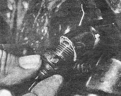
Photo 27.3. Oil pressure switch with washer (engine 1.3).
4. The cylinders are lubricated by splashing oil taken from the sump.
5. In hydraulic tappets, the oil is under pressure, which allows for optimal valve clearances under any conditions. On engines 1.6 and 1.8, the oil pressure in the tappets is regulated by a special valve located in the cylinder head (see photo).
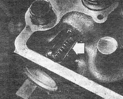
Photo 27.5. Oil pressure control valve located in the cylinder head (shown by arrow).
6. The crankcase ventilation system is designed to remove oil vapors and associated gas (working gas passing through the piston rings) from the crankcase to the air cleaner, where they return to the engine and are burned there during the normal combustion cycle.
7. On 1.3 engines, the crankcase ventilation system includes an oil separator bolted to the cylinder block. Although not included in the maintenance, the oil separator can be removed for cleaning (see photo).
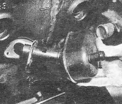
Photo 27.7. Oil separator for crankcase ventilation system.
8. On engines 1.6 and 1.8, one of the crankcase ventilation hoses is connected to the camshaft cover (see photo). There is a filter inside the lid that should be periodically cleaned in kerosene.
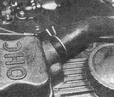
Photo 27.8. Crankcase ventilation hose connected to the camshaft cover (engines 1.6 and 1.8).
9. On all engines, breather hoses should be periodically cleaned and replaced as necessary.
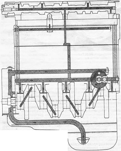
Pic. 1.22. Engine lubrication diagram (lengthwise cut) - engine 1.
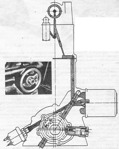
Fig.1.23. Engine lubrication diagram (cross section - 1.3 engine:1. The inset shows the oil filter base and relief valve.
Visitor comments