
Crankshaft
1. Inspect the crankshaft connecting rod and main journals for abrasion and scratches and measure them in several places using a micrometer. If the journals are heavily worn or their shape is different from cylindrical (For tolerance limits see Specifications), the crankshaft must be bored.
2. Wear of the connecting rod journals and connecting rod bearings is usually accompanied by a distinct metallic knock, especially noticeable at low speeds, and some loss of oil pressure.
3. Wear of the main journals and bearings is accompanied by strong vibration and noise, which gradually increase as engine speed increases, and, as in the previous case, some loss of oil pressure.
4. Boring of the crankshaft must be carried out by a specialist who will select the liners of the required repair size.
Connecting rod and main bearing shells
5. Inspect the connecting rod and main bearing shells for general wear, abrasion, pitting and scratches. The bearings should be matte grey. In the case of lead-indium bearings, the slightest trace of copper indicates severe wear and the need to replace the bearings. We strongly recommend replacing the bearings regardless of their condition during any major engine overhaul.
b. Commercially available repair bearing sizes are designed for specific crankshaft sizes after boring. In practice, the bearing dimensions are slightly larger than indicated, because During their manufacture, the working gap was taken into account in advance.
7. The dimensions of the main and connecting rod bearings are indicated on the reverse side of the bearings. Standard size earbuds are marked "STD" or ".00", and on the repair size inserts it is indicated how much the size has been reduced compared to the standard (For example "0.020 u/s"). This marking is only on bearings intended for replacement. There are no markings on the bearings originally installed on the machine.
Cylinders
8. Cylinders should be inspected for loss of shape, abrasion and scratches. The inspection should begin from the top of the cylinders. If there are ridges corresponding to the top point of the piston stroke, then this indicates wear on the cylinders. A sign of excessive wear on the cylinders and piston rings is an increase in oil consumption and a blue tint in the exhaust gases.
9. Measure the inside diameter of the cylinders just below the ridges and compare it with the diameter at the bottom of the cylinders, which is not subject to wear. If you don't have an internal micrometer or dial gauge, you can use a piston with the rings removed and measure the clearance between them with the cylinder walls at various places using a feeler gauge. If cylinder wear exceeds permissible limits (see Specifications), the cylinders need boring. The following points should be kept in mind:
- A. The pistons and cylinders are carefully matched to each other during the manufacturing process of the machine. The actual diameter of the piston is indicated by numbers on its bottom. The same numbers stamped on the crankcase indicate the bore diameter of the cylinder.
- b. After boring the cylinders, you should very carefully measure their diameter and select pistons of a repair size that would provide the required clearance between the piston and the cylinder.
- V. When selecting pistons, their diameter is measured along the bottom of the skirt.
10. If wear is close to the maximum permissible, you can select special new piston rings that allow you to partially compensate for the wear.
Connecting rods
11. Inspect the connecting rod bearing caps to see if they have ever been worn away in an attempt to remove wear. If traces of sharpening are detected, the defective connecting rods should be replaced.
12. Visually inspect the connecting rods for straightness and, if in doubt, have them checked by a specialist using instruments.
13. The piston pins have a fixed fit in the upper heads of the connecting rods. As mentioned earlier, the disconnection of pistons and connecting rods can only be done by a specialist.
Pistons and piston rings
14. If you are not going to change the pistons and (or) piston rings, the rings should be removed from the pistons. Unclench the top ring enough so that you can insert 3 metal strips or 0.38 mm feeler gauges under it, and pull the ring off the piston along these strips, which will avoid scratching or damaging the piston.
15. Repeat this procedure for the second and third rings.
16. Mark the rings or arrange them in order so as not to mix them up during installation. The top ring can be installed on either side, and the second ring on the top surface has the inscription "TOP".
17. Inspect the pistons for cracks, damage in the groove area and abrasion.
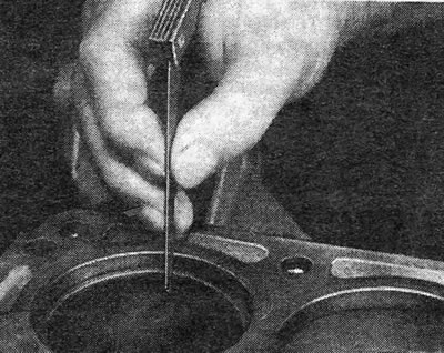
18. Clean the ring grooves using a piece of an old piston ring, being careful not to scratch the pistons or cut yourself, as piston rings have sharp edges (see photo).
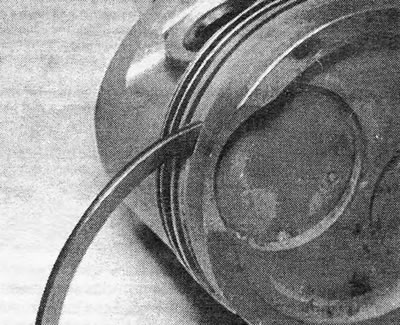
Photo 32.18. Cleaning the piston ring groove.
19. Check the rings in their cylinders. To do this, lower the ring into the lower (unworn) cylinder part (so that the ring goes without distortion, you can push it deep into the cylinder with a piston). Measure the ring lock and check if it is within acceptable limits (see Specifications). If the lock size is too large, the rings should be replaced. If there is significant wear on the ring grooves, it may be necessary to replace the pistons.
20. New pistons are usually supplied with piston rings. If you are only changing the rings, you should contact a specialist who will adjust the pistons to the new rings.
21. When installing new rings (or new pistons with rings) in old cylinders the top ring should have a recess to fit the existing comb (or the comb must be removed).
22. Check the size of the locks of the new rings (see paragraph 19). If the ring is too tight in its groove, it can be sharpened using a whetstone or carborundum sandpaper. If the lock is too small, you can lightly grind off the ends of the ring.
23. New pistons are selected from among the available repair sizes after measuring the cylinder diameters (see paragraph 9). When installing new piston rings, remove varnish deposits from the cylinder walls using sandpaper or a honing head mounted on an electric drill. When using sandpaper, remove plaque using cross-shaped movements at an angle of 60 degrees to the cylinder axis.
Flywheel
24. If the teeth of the flywheel ring gear are severely worn or damaged, the ring gear should be replaced.
25. Drill or saw a hole in the old crown at the base of two teeth (Be careful not to damage the flywheel). Split the crown over the drilled hole using a chisel (this should be done with safety glasses). Separate the ring from the flywheel and remove it.
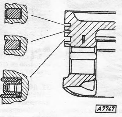
Pic. 1.25. Piston ring installation diagram
26. Heat the new crown in an oven or flame to 180-230°C. Be careful not to overheat the crown, as... it may lose its hardening.
Pic. 1.26. Checking the piston ring lock size
27. Place the crown on the flywheel, carefully hammer it into place and leave to cool. Shrinkage during cooling will ensure a secure, stationary fit of the crown.
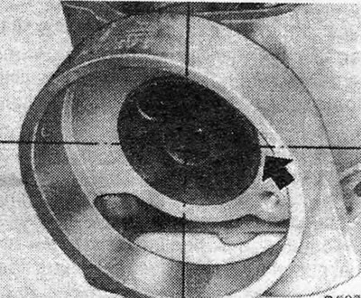
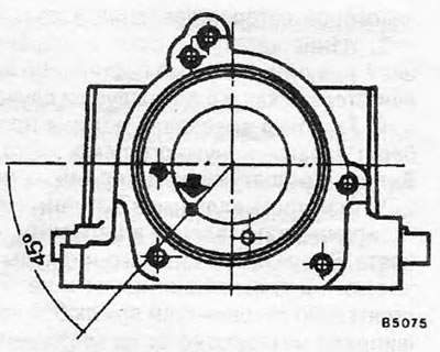
Pic. 1.27. Point at which to drill a hole in the camshaft housing - 1.3 engine
28. If the surface of the flywheel touching the driven disc has scratches or hairline cracks caused by overheating, the flywheel can be surface treated (unless its thickness decreases beyond acceptable limits). If surface treatment is not possible, the flywheel should be replaced.
Pic. 1.28. Point at which to drill a hole in the camshaft housing - 1.6 engine
29. When the needle bearing located in the center of the crankshaft flange wears out, fill it with lubricant and drive a rod of similar diameter inside. Due to the hydraulic pressure generated in this case, the bearing will come out of its seat. When installing a new bearing, check that it faces up with the chamfer facing inward. On engines with numbers greater than 14089444, the crankshaft no longer includes a needle bearing. Master disk (Automatic transmission).
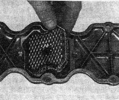
Pic. 1.29. Filter in the camshaft housing cover - engines 1.6, 1.8 and 2.0
30. If the starter ring gear on the drive disk needs to be replaced, the driven disk assembly will have to be replaced.
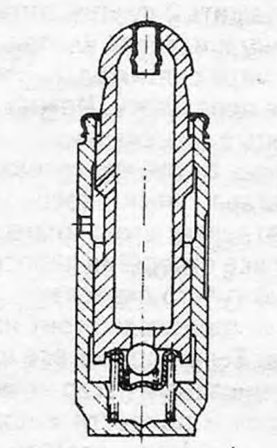
Pic. 1.30. Hydraulic pusher (incision)
Camshaft
31. With the camshaft removed, inspect its bearings for obvious wear and pitting. If defects are found, the camshaft housing will most likely have to be replaced.
32. The camshaft itself should show no signs of abrasion on the journals or cam contours. If there are obvious defects, replace the camshaft. When replacing the camshaft on older models with a 1.3 or 1.6 engine, the camshaft housing will have to be modified in some way to improve the lubrication system. To do this, temporarily install the old camshaft in its place in the crankcase without a locking plate. Punch a hole in the crankcase with a punch at a point located on the circumference of the camshaft journal and using a drill with a diameter of 3.0 mm, drill a hole 16.0 mm deep (no more than that) (see fig.1.27 and 1.28).
33. The locking plate must not show signs of wear or grooves. In any case, check the axial movement of the camshaft and install a new plate if necessary.
34. Whenever the engine is overhauled, the front camshaft housing oil seal should be replaced. On engines 1.6 and 1.8, the camshaft housing cover contains a filter, which should be removed, thoroughly washed in kerosene, allowed to dry and put back in place (see fig.1.29).
Camshaft timing belt
35. Carefully inspect the belt for cracks, abrasions and deformation of the teeth. If there are obvious defects, replace the belt.
36. If the belt has been used for more than 48,000 km, it is recommended to replace it, regardless of its condition.
37. If you are not going to change the belt, then before removing it you should note the direction of its movement. It is even recommended to mark those teeth on the sprockets that were engaged with the belt before it was removed. This will avoid an increase in belt noise during operation after it is reinstalled.
Valve lifters, rockers and thrust pads
38. If the hydraulic pusher is defective, it must be replaced. For information on disassembling and cleaning the tappets, see Chapter 13, Section 3.
39. Inspect the rockers and thrust pads for wear and grooves. Replace defective parts.
Cylinder block and plugs
40. Thoroughly clean the unit outside and inside. Check the plugs for signs of corrosion. If the engine has high mileage, it is recommended to replace the plugs, regardless of their condition.
41. To remove the old plug, drill through it, insert a suitable rod and, using it as a lever, pull out the plug.
42. Thoroughly clean the hole, coat the new plug around the edges with sealant and install it in place, making sure that it does not become deformed. If possible, use aluminum-coated plugs.
Visitor comments