
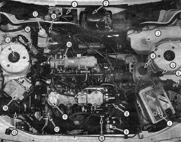
View under the hood - model 1.8 1987, 18SE engine and L3 Jetronic fuel injection system: 1. Wiper motor; 2. Heater fan motor; 3. Washer reservoir; 4. Coolant reservoir; 5. Fuel system relay; 6. Ignition coil; 7. Battery; 8. Ignition distributor (distributor); 9. Radiator cooling fan; 10. Engine oil level meter; 11. Oil filler cap; 12. Thermostat housing; 13. Air purifier; 14. Air flow sensor; 15. Mounting the suspension strut; 16. Ignition system monitoring device; 17. Brake fluid reservoir; 18. Vacuum brake booster; 19. Damper valve housing
1. In 1987, significant changes were introduced for the 1.6 and 1.8 liter engines, and a 2.0 liter engine was also introduced. Modified engines can be easily identified by the position of the oil filler cap, which is now located next to the camshaft cover on the belt side. Additionally, the top belt cover is secured with spring clips instead of the bolts used on earlier models.
2. The main engine modifications are the following:
3. Cylinder block: Its structure has been strengthened to reduce vibration and engine noise, which also reduces bore and bearing wear.
4. Head: The profile of the combustion chamber has been changed, resulting in an increase in the combustion chamber area in the cylinder head, and the inlet ports have also been changed on engines with fuel injector. In addition, the capacity of the cylinder cooling jacket has been reduced, which has shortened the warm-up period.
5. Crankshaft: The #1 crankshaft counterweight now has a segmented disc (engines with a volume of 1.8) or serrated lock washer (engines with a displacement of 2.0), to ensure the combination of control devices for ignition and fuel supply systems with the position of engine speed/crankshaft position.
6. Connecting Rods and Cranks: The diameter and bore width of the smaller end of the connecting rod have been changed, and narrower crank studs have been installed. For optimal engine balance, connecting rods are divided into 16 weight categories.
7. Additional changes were made to the design of pistons and rings, valves and their springs, camshaft and oil pump.
8. Apart from those operations described in the Appendix, all other maintenance, repair and disassembly procedures are similar to those presented for engines on earlier models, and all information provided below should be used only in accordance with the information provided. available in Chapter 1.
2.0 l engine - general information
9. The design of this engine is similar to the 1.8 liter engine, and the maintenance, repair and disassembly processes for this engine are also similar to the 2.0 liter engine. The difference in specifications is indicated in the Specifications given at the beginning of this Chapter. In cases where specification information is not available in this Chapter, information related to the 1.8 liter engine can be used.
Camshaft timing belt (1.6,1.8 and 2.0 l, since 1987) - replacement
Note: Correct timing belt adjustment requires the use of a special tool, available from Vauxhall. Approximate adjustments can be made using the method described below, but ideally it is recommended that you contact a specialist to check the correctness of the adjustment using special equipment.
10. Disconnect the battery ground wire and, for easier access, remove the air cleaner assembly as described in Chapter 3.
11. Drain all fluid from the cooling system as described in Chapter 2.
12. Loosen the generator adjustment link and mounting bolts (see photo 3.12), move the generator towards the engine and remove the drive belt from the pulleys.
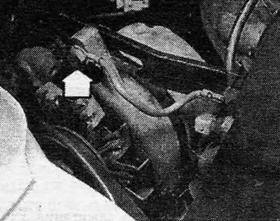
Photo 3.12 Bolt of the generator adjustment connecting element (indicated by arrow)
13. Release the retaining clips and remove the top timing belt cover (see photo 3.13).
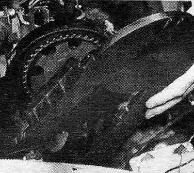
Photo 3.13 Removing the top cover of the timing belt
14. Using a wrench on the camshaft pulley bolt, rotate the camshaft until the No. 1 piston is in the fire position. This position will be indicated by the projection on the camshaft pulley being level with the indicator on the oil pump housing, and the projection on the camshaft sprocket being aligned with the sprocket on the inner periphery of the timing belt cover (see photo 3.14 A and B).
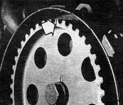
Photo 3.14 A Align the protrusion on the camshaft chain ring (indicated by arrow)...
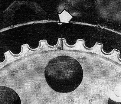
Photo 3.14 V....with an asterisk on the inner cover of the timing belt (indicated by an arrow)
15. Raise and support the front of the vehicle, and then remove the right front wheel.
16. Using a suitable Allen wrench, remove the four bolts securing the crankshaft pulley to the timing belt sprocket and remove the pulley (see photo 3.16 A and B).
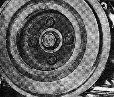
Photo 3.16A Unscrew the four crankshaft pulley mounting bolts...
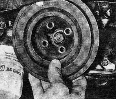
Photo 3.16B....and remove the pulley
17. Release the retaining clips and remove the timing belt intermediate cover from the water pump area.
18. Using a suitable Allen wrench or other appropriate tool, loosen the three bolts securing the coolant pump, then rotate the pump in place to release tension on the timing belt. The pump can be moved by grasping the tab located on the side of its casing (see photo 3.18 A and B).
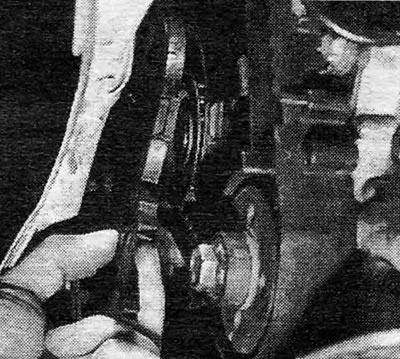
Photo 3.18 A Loosen the upper bolt of the cooler pump (A), front bolt (IN)...
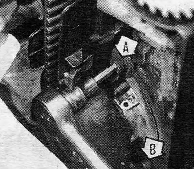
Photo 3.18 V....and rear bolt (WITH), then advance the pump using the protrusion (D)
19. If you intend to continue using the same belt, mark the direction of movement with chalk, then remove it from the three sprockets (see photo 3.19).
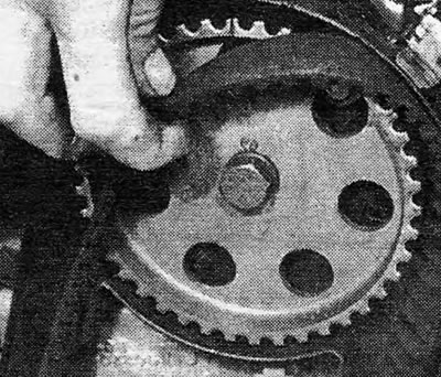
Photo 3.19 Remove the timing belt from the chain rings
20. Check the condition of the belt, and replace it if there is the slightest sign of cracking, tearing, oil contamination or general wear.
21. Without changing the position of the crankshaft and camshaft, place the belt on top of the chain rings. Tension the belt slightly while moving the coolant pump, then temporarily tighten the pump bolts.
22. Reinstall the crankshaft pulley (without tightening its mounting bolts), and check that all marks match, as previously described in Section 14. Now rotate the crankshaft through two complete cycles, in the direction of normal rotation, and check that the pointers can again be fully aligned. If this is not the case, loosen the belt tension and change its position on the crankshaft chain rings until all indicators can be aligned properly.
23. Loosen the coolant pump mounting bolts and move the pump to achieve belt tension. The tension will be correct when it can be turned approximately 90 degrees by hand at a point midway between the crankshaft and camshaft sprocket rings on the straight side of the belt. Once the correct belt tension is achieved, tighten the coolant pump bolts, rotate the camshaft one full cycle, and check the tension again. Repeat this procedure until you reach the correct belt tension.
24. Install the timing belt intermediate cover onto the coolant pump.
25. Reinstall the camshaft pulley and secure it with four bolts, tightened to the required degree.
26. Reinstall the top timing belt cover and secure it with the retaining clips.
27. Reinstall the generator drive belt and adjust its tension as described in Chapter 2.
28. Reinstall the wheel and lower the vehicle to the ground.
29. Install the air cleaner as described in Chapter 3, fill the cooling system as described in Chapter 2, then connect the battery ground wire.
Front camshaft oil seals (1.6, 1.8 and 2.0 liters, 1987 onwards) - replacement
30. Remove the camshaft timing belt as described above.
31. Remove the air hose, if installed, then remove the bolts and remove the camshaft cover. Mark the position of the cable clamps under the mounting bolts to facilitate reassembly. Remove the cover gasket.
32. Unscrew the central mounting bolt and remove the sprocket from the camshaft (see photo 3.32). To prevent the camshaft from rotating while removing this bolt, use a flat section wrench positioned between #3 and #4 of the camshaft.
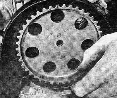
Photo 3.32 Removing the chain ring from the camshaft
33. Unscrew the central bolt of the crankshaft chain ring without changing the set position of the crankshaft. To prevent rotation of the crankshaft while removing this bolt, it may be sufficient to engage the gear and handbrake (only for manual transmission); A better way would be to remove the flywheel bottom cover plate and lock the transfer ring with a large screwdriver or something similar.
34. Remove the sprocket from the crankshaft. If it holds tightly, reinstall the bolt, two to three turns, and then remove the sprocket using a two-handed puller (see photo 3.34 A and B).
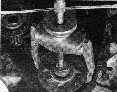
Photo 3.34A Use a puller, if necessary, to remove the chain ring from the crankshaft...
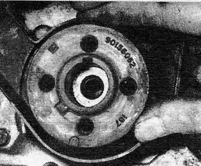
Photo 3.34B....then remove the chain ring from the crankshaft
35. Carefully release the Woodroof key, then remove the spacers located behind the key (see photo 3.35 A and B).
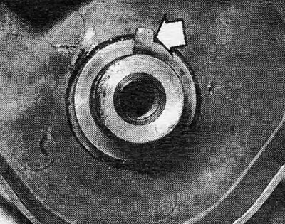
Photo 3.35A Remove the Woodroffe key (indicated by arrow)...
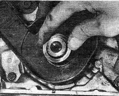
Photo 3.35V... and behind it the gasket (And)
36. Remove the two top bolts securing the rear timing belt cover to the camshaft housing and release the electrical wire from the top retaining clip. Remove the two bottom bolts securing the rear belt cover to the oil pump housing, then remove the cover from underneath (see photo 3.36 A and B).
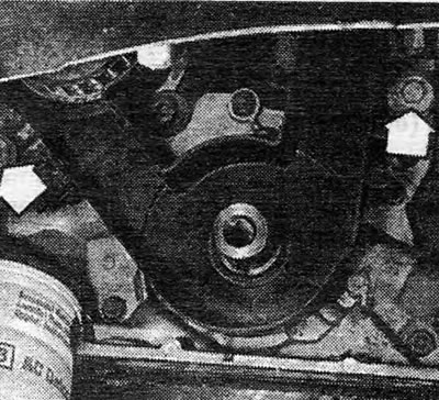
Photo 3.36A Rear toothed belt cover mounting bolts (indicated by arrows)
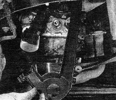
Photo 3.36B Removing the rear toothed belt cover
37. Punch or drill a small hole in the center of the oil seal. Screw a self-tapping screw into it and pull it out by grasping the screw with pliers.
38. Clean the gasket installation location in the camshaft housing, then lubricate the jaws and sides of the new gasket with engine oil.
39. Install the new gasket with its jaws facing inward and push it into place using a piece of tubing and a mallet. Be careful when installing to avoid damaging the gasket jaws; If the new gasket has a protective sleeve, be sure to use it.
40. Install the timing belt cover and secure it with four bolts.
41. Place the shims on the crankshaft and reinstall the Woodroof key and timing belt sprocket. Replace the chain ring retaining bolt and tighten it to the required degree (see photo 3.41).
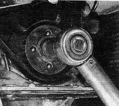
Photo 3.41 Tighten the chain ring mounting bolt to the required degree
42. Reinstall the camshaft chain ring and secure it with the mounting bolt, tightened to the required degree.
43. Using a new gasket if necessary, reinstall the camshaft cover. Tighten the mounting bolts gradually in a diagonal sequence to the required degree. Connect the sleeve.
44. Install and adjust the camshaft timing belt, referring to the beginning of this Section for information.
Camshaft (1.6, 1.8 and 2.0 liters, since 1987) - removal and installation
45. Camshaft removal and installation procedures are described in the following section on cylinder head removal and installation. The camshaft housing bolts also secure the cylinder head, so when these bolts are removed there is a very high chance that the gasket will be damaged. For this reason, if you intend to remove the camshaft, the cylinder head must be completely removed.
Cylinder head (1.6,1.8 and 2.0 liters, since 1987) - removal and installation
Note: The following procedure describes the removal and installation of the cylinder head, complete with pipes, on fuel injection engines. This process can also be used on carbureted engines and if necessary please contact Chapter 3 for details on electrical and fuel line connections for carburetor engines.
46. The cylinder head should only be removed when the engine is cold, otherwise there is a risk of damage.
47. Disconnect the battery ground wire.
48. Remove the air cleaner assembly as described in Chapter 3.
49. Drain all fluid from the cooling system as described in Chapter 2.
50. Disconnect the radiator and heater hoses from the cylinder head and pipeline.
51. Disconnect the spark plug high voltage wires, marking them as necessary, then remove the distributor cover (ignition distributor). On 1.6 liter engines, remove the distributor as described in Chapter 4.
52. Remove the bolt securing the crankshaft housing air hose to the side of the cylinder head (see photo 3.52).
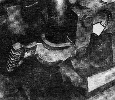
Photo 3.52 Unscrew the crankshaft housing air tube mounting bolt (indicated by arrow)
53. Loosen the connecting sleeve of the air pipe at the camshaft housing, remove the oil level gauge, and unscrew the two bolts securing the air pipe from the block. Disconnect the sleeve completely and remove the entire air tube structure (see photo 3.53 A and B).
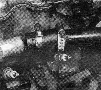
Photo 3.53A Disconnect the air tube sleeve from the camshaft housing
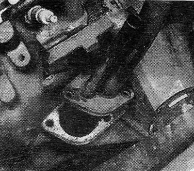
Photo 3.53B Removing the air tube structure
54. Disconnect the choke cable from the carburetor or the choke housing, depending on the model.
55. Disconnect the electrical wires and wiring plugs from the carburetor, fuel injection system components, pipeline and cylinder head as necessary. Mark all wires when removing them to avoid confusion during assembly; If necessary, refer to Chapter 3 or the following Sections for further information. Once all the wiring is disconnected, you can move it away from the engine.
56. Disconnect and plug the fuel lines from the carburetor and injector system, depending on the model. Also on models with a carburetor, remove the fuel pump.
57. Disconnect the brake booster vacuum hose at the inlet of the pipeline (see photo 3.57).
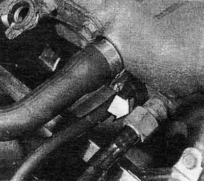
Photo 3.57 Connecting the brake booster vacuum hose to the pipeline (indicated by arrow)
58.Disconnect the exhaust pipe from the pipeline.
59. Disconnect hoses from auxiliary air valve (see photo 3.59), then remove the valve from the camshaft housing.
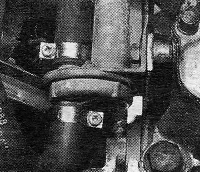
Photo 3.59 Hose connections at the auxiliary air valve
60. Unscrew the bolts and remove the camshaft cover (see photo 3.60).
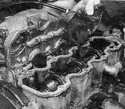
Photo 3.60 Removing the camshaft cover
61. Loosen the generator adjusting fasteners and mounting bolts, move the generator toward the engine and remove the drive belt from the pulleys.
62. Remove the timing belt covers and release the belt tension as described in paragraphs 13-18 earlier in this Section.
63. Remove the timing belt from the camshaft sprocket, then remove the center mounting bolt and remove the sprocket from the camshaft. To prevent the camshaft from rotating when removing this bolt, place a flat wrench between the Nos. 3 and 4 camshaft lobes.
64. Remove the two bolts securing the rear timing belt cover to the camshaft housing (see photo 3.64)
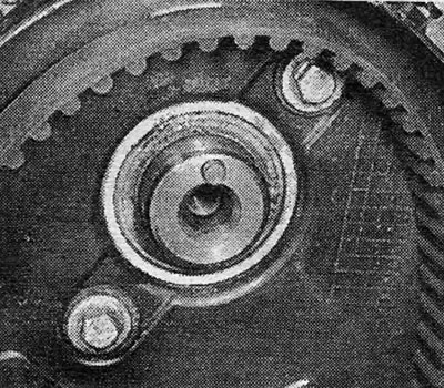
Photo 3.64 Bolts securing the rear cover of the timing belt to the camshaft housing
65. Remove the cylinder head bolts in the reverse order shown in Figure 13.1; loosen the bolts 1/4 turn each time, then 1/2 turn in sequence until all bolts are loose. This process is very important to avoid damaging the cylinder head or camshaft housing. Be sure to throw away the old bolts and purchase new ones.
66. Remove the rear timing belt cover from the camshaft housing, then lift the housing up and away from the mounting tabs (see photo 3.66).
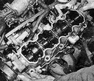
Photo 3.66 Removing the camshaft casing from the cylinder head
67. Remove the levers and plates from the cylinder head. Remove the valve lifters and place them in a container of clean engine oil to prevent them from drying out. Keep all items in their original order (see photo 3.67 A, B and C).
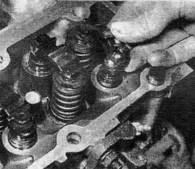
Photo 3.67A Remove the levers...
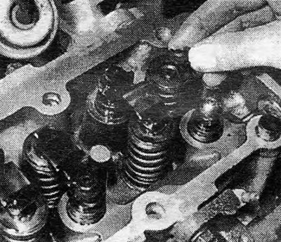
Photo 3.67B... behind them are plates...
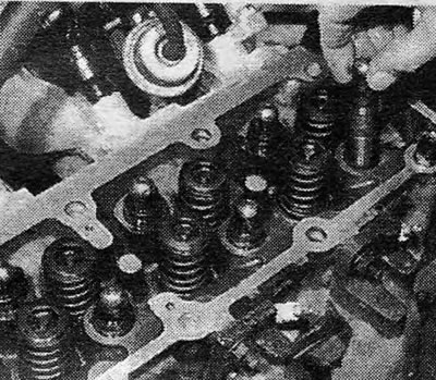
Photo 3.67C... and remove the valve lifters
68. Remove the cylinder head (see photo 3.68). If it is stuck, carefully pry it out with a plastic mallet. Remove the head gasket.
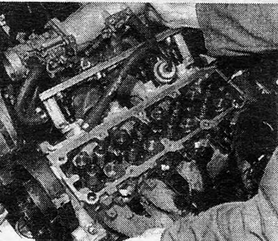
Photo 3.68 Removing the cylinder head
69. If further disassembly of the cylinders is required, refer to the procedures given in chapter 1.
70. Clean the head and cylinder block of carbon by carefully scraping it off. Cover cooler passages and other openings with film or cloth to prevent carbon or dirt from entering. Blot excess oil from the bolt holes; hydraulic pressure can cause the block to crack when screwing in the bolts if there is excess oil in their holes.
71. Once everything is clean, place a new cylinder head gasket on the block so that the word "OBEN" could be read from above (see photo 3.71).
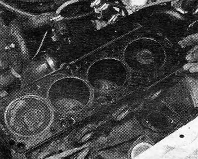
Photo 3.71 Install a new gasket with the word "OBEN", located on top
72. If the crankshaft was rotated when removing the cylinder head, reinstall it so that the No. 1 piston is in the fire position.
73. After you have thoroughly cleaned the mating surfaces, place the cylinder head on the block so that the locating lugs fit into their holes.
74. Reinstall the hydraulic lifters, plates and levers into the cylinder head in the original order. When installing new hydraulic lifters, first place each one in a container of clean engine oil and then squeeze it by hand several times.
75. Temporarily place the chain ring on the camshaft and check that the pointer is in the correct position. If necessary, reinstall the shaft to the correct position, then remove the chain ring again.
76. Apply hardening compound to the mating surfaces of the cylinder head and camshaft housing, and install the housing onto the cylinder head.
77. Install new cylinder head bolts and tighten them in a spiral pattern as shown in Figure 13.1 to the required torque. Note that these bolts are tightened in five stages, with the last four stages requiring bolt angular measurements. You can use a template or a special measuring tool for this purpose (see photo 3.77). These tools can be purchased from manufacturers at very reasonable prices, or they can be borrowed from lucky owners.
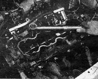
Photo 3.77A First tighten the cylinder head bolts to stage 1...
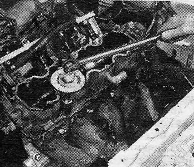
Photo 3.77B... and then to the correct angular value in four more stages
78. Install the two bolts securing the rear timing belt cover to the camshaft housing.
79. Install the camshaft chain ring and secure its central bolt, tightening it to the required degree (see photo 3.79).
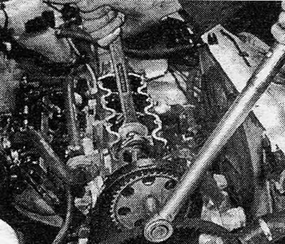
Photo 3.79 Hold the camshaft and tighten the chain ring bolt to the required degree
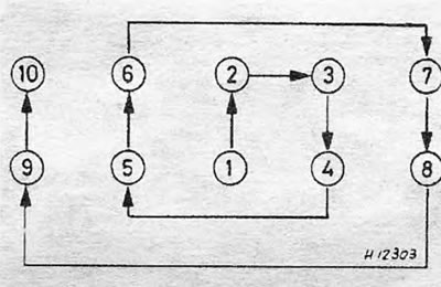
Figure 13.1. Cylinder Head Bolt Torque Sequence - Work in a spiral pattern as shown
80. Check that the alignment marks of the camshaft chain ring and the crankshaft pulley are in the correct position, as described earlier, then install and tension the timing belt as described in paragraphs 21 - 27 of this Section.
81. Install the camshaft cover using a new gasket.
82. Install and tension the alternator drive belt as described in Chapter 2.
83. The processes for installing the remaining parts are carried out by performing the steps taken during disassembly in reverse order. When complete, fill the cooling system as described in Chapter 2.
84. After the engine has started and reached normal operating temperature, check and, if necessary, adjust the idle speed (if it is regulated), and then retighten the cylinder head bolts to the required degree in stage 5.
Sump (1.6,1.8 and 2.0 liters, since 1987) - removal and installation
85. Remove the plug and allow the engine oil to drain into a suitable container. After draining the oil, reinstall the plug.
86. Raise and support the front of the car.
87. Disconnect the exhaust pipe from the pipeline and from the ball mount, and remove the front section of the exhaust pipe from the vehicle.
88. Unscrew the bolts and remove the cover from the flywheel (see photo 3.88).
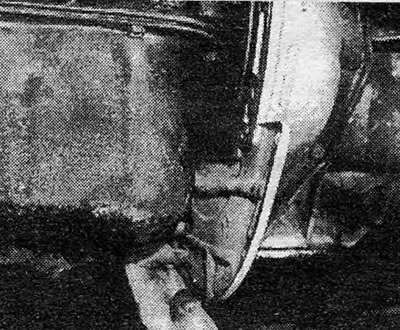
Photo 3.88 Removing the flywheel cover
89. Gradually loosen and then remove the oil pan mounting bolts.
90. Lower the oil pan down under the car (see photo 3.90).
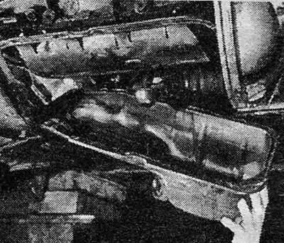
Photo 3.90 Removing the oil pan
91. If the oil pan is being removed to gain access to the crankshaft and bearings, remove the old oil pickup tube and shield plate as follows.
92. Remove the two bolts securing the oil pickup tube to the oil pump housing (see photo 3.92), and remove the bolt securing the support bracket to the edge of the crankshaft housing.
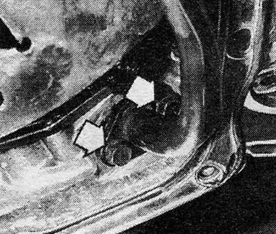
Photo 3.92 Oil pickup tube mounting bolts (indicated by arrows)
93. Remove the old oil pickup tube, followed by the shielding plate (see photo 3.93).
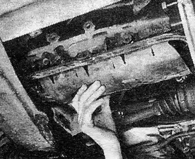
Photo 3.93 Removing the shielding plate
94. Remove the double-sided rubber gasket from the shielding plate (see photo 3.94).
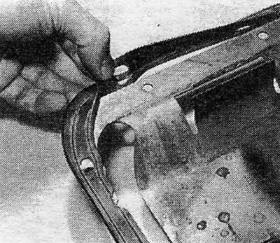
Photo 3.94 Removing the double-sided rubber gasket from the shielding plate
95. Clean the oil sump thoroughly and purchase a new gasket if the old one shows even the slightest signs of damage. The O-ring on the oil pickup tube must be replaced in any case (see photo 3.95).
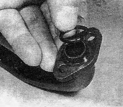
Photo 3.95 0-ring gasket of oil pickup tube
96. Install the gasket onto the shield plate, then install the shield plate in place, using the two oil pan bolts to temporarily hold it in place.
97. Install the oil pickup tube and secure it with two bolts on the flange and a support bracket bolt. Remove the two bolts that temporarily secure the shield plate, then lift the oil pan into place. Install the bolts and tighten them gradually, in a diagonal sequence, to the required degree.
98. Reinstall the flywheel cover and front exhaust pipe section.
99. Lower the vehicle to the ground and fill the engine with oil.
Oil pump (1.6, 1.8 and 2.0 liters, since 1987) - removal and installation
100. Remove the camshaft timing belt and its covers, as described in paragraphs 30 - 36 of this Section.
101. Remove the oil pan as described above in this Section.
102. Remove the oil filter, and disconnect the oil pressure switch wire from the oil pump housing (see photo 3.102).
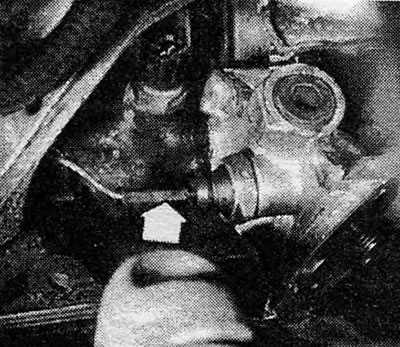
Photo 3.102 Connecting the electrical wire of the oil pressure switch (indicated by arrow)
103. Unscrew the mounting bolts and remove the oil pump casing from its guides on the cylinder block (see photo 3.103 A and B). Remove the gasket.
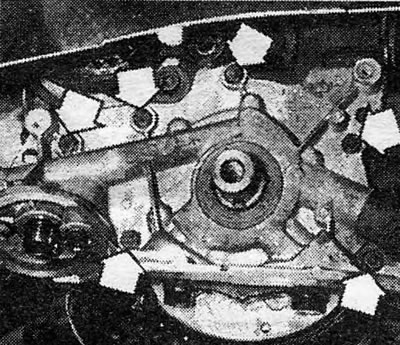
Photo 3.103 A Unscrew the oil pump casing mounting bolts (indicated by arrow)...
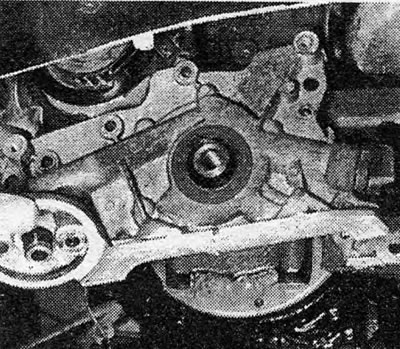
Photo 3.103 B... and remove the casing
104. If further disassembly of the oil pump is required, contact Chapter 1.
105. Clean all traces of old gasket from the mating surfaces of the pump housing and cylinder block.
106. Apply curing compound to the new gasket and place it on the block lugs (see photo 3.106).
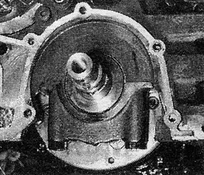
Photo 3.106 Place the new housing gasket over the mounting tabs
107. To protect the oil gasket lips when installing the oil pump, wrap the crankshaft lip with film and thoroughly lubricate the gasket lips.
108. Carefully place the cover in place and unwind the film.
109. Install the mounting bolts and tighten them to the required degree.
110. Install a new oil filter and connect the oil pressure switch electrical wire.
111.Install the oil sump as described above in this Section.
112. Install the timing belt as described above in paragraphs 40-44 earlier in this Section.
Front crankshaft oil gasket (from the pulley side) — (1.6,1.8 and 2.0 liters, since 1987) - removal and installation
113. Remove the camshaft timing belt and its cover (belt), as described in paragraphs 30-36 earlier in this Section.
114. Punch or drill a small hole in the front surface of the oil gasket and screw a self-tapping screw into it. Grasp the screw with pliers and pull out the gasket.
115. Wrap a little film around the crankshaft boss and thoroughly lubricate the gasket lips.
116. Using a piece of tubing and a mallet, carefully work the gasket into place.
117. Reinstall the timing belt as described above in paragraphs 40-44 of this Section.
Engine (volume 2.0 liters) - removal and installation
118. Details of the engine removal and installation process are essentially the same as for earlier engines, described in Chapter 1. If you need information about the details of the fuel system or ignition system, please refer to the relevant Sections of this Chapter (Additions). Hydraulic Valve Lifters - General Information
119. For those engines that have a high mileage or have had many repairs in the past (especially if there has been an oil change), It is quite possible that hydraulic valve lifters may suffer from severe internal contamination, which in extreme cases will result in increased engine noise and accelerated wear. To minimize engine problems, it is recommended that the valve lifters be disassembled and cleaned each time the cylinder head is disassembled. Note that there are no replacement parts for valve lifters, so if any part of the system fails, it must be completely replaced.
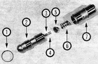
Photo 3.119 Hydraulic valve lifter parts 1. Ring; 2. Plunger; 3. Ball; 4. Smaller spring; 5. Plunger cap; 6. Large spring; 7. Cylinder
120. Carefully remove the ring from the top of the valve. It is usually quite possible to remove the ring by hand - if you use tools to do this, be extremely careful not to damage the ring.
121. Remove the plunger from the cylinder, followed by the spring.
122. Using a small screwdriver, carefully remove the cap from the plunger base. Remove the spring and ball from under the cap, being careful not to lose them.
123. Carefully clean all components using paraffin or other suitable solvent, paying particular attention to the machined surfaces of the cylinder (its inner surface), and piston (external). Dry all parts thoroughly using a non-fraying cloth. Check the springs carefully for signs of damage - and if the condition of the springs leaves much to be desired, the entire valve lifter will need to be replaced.
124. Lightly lubricate all components with clean engine oil of the appropriate type, then assemble the structure as follows.
125. Replace the plunger and place the ball in place at the base of the plunger (see photo 3.125).
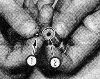
Photo 3.125 Place the ball (1) in his place (2) at the base of the plunger
126. Reinstall the smaller spring into the plunger cap, then reinstall the cap and spring, making sure the spring is seated on the ball. Lightly press the cap flange in a circle using a small screwdriver until the flanges are completely seated in the groove in the base of the plunger (see photo 3.126 A and B).
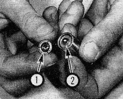
Photo 3.126A Spring (1), placed in the plunger cap, and the ball (2), located in its place in the plunger
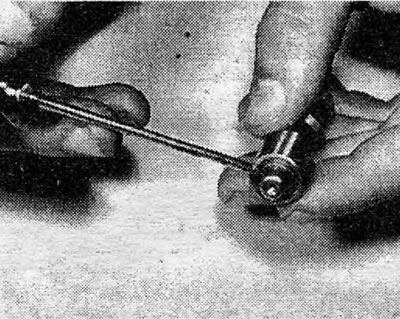
Photo 3.126B Place the cap flange in the plunger groove
127. Place the large spring on top of the plunger cap, making sure it is seated correctly, and insert the plunger and spring into the cylinder (see photo 3.127 A and B).
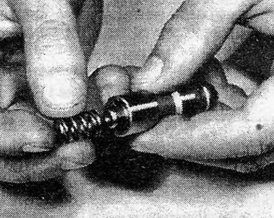
Photo 3.127A Place the spring over the plunger cap...
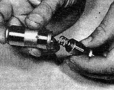
Photo 3.127B...then install the plunger and spring structure into the cylinder
128. Place the ring on the top of the plunger and gently press the plunger with your hand until the ring, when moving down, is completely seated in the groove in the cylinder (see photo 3.128).
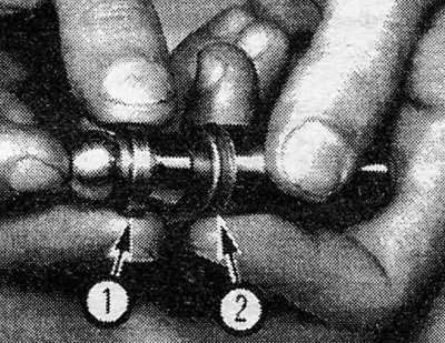
Photo 3.128 Put on the ring (1) over the plunger and slide it into the groove (2) in a cylinder
Visitor comments