
1. The cylinder head can only be removed from a cold engine, because otherwise it may become deformed.
2. Disconnect the wire "masses" battery
3. Drain the coolant (see chapter 2), saving it for later use.
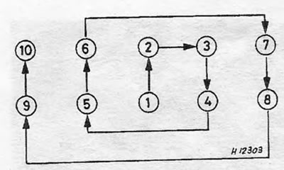
Pic. 1.3. The tightening sequence for the cylinder head bolts is a spiral tightening sequence.
4. On carburetor models, remove the air cleaner. On injection models, disconnect the air intake duct at the throttle body.
5. Disconnect the fuel lines leading to the fuel pump (carburetor models) or fuel manifold and fuel pressure regulator (injection models). Be prepared for fuel spills.
6. Disconnect control cables and electrical wiring from the carburetor or throttle body (depending on model).
7. Disconnect the heater hoses and vacuum tube from the intake manifold.
8. Disconnect the wire from the temperature sensor on the intake manifold or throttle body (depending on model) (see photo).
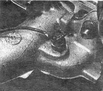
Photo 8.8. Cooling system thermal switch wiring (engine 1.3).
9. Remove the generator drive belt (see chapter 2).
10. Remove the camshaft belt cover and set piston N1 to the mixture ignition stroke, as described in section 5.
11. Remove the distributor or disconnect the distributor cover and the low voltage wire connector. On the latest injection models, disconnect the high voltage wire from the coil so that the distributor can be removed along with the cylinder head.
12. Remove the camshaft cover.
13. Check that the mark on the camshaft sprocket matches the mark on the camshaft housing.
14. Disconnect the lower exhaust pipe from the manifold.
15. Loosen the water pump bolts, move it to reduce the tension of the timing belt and remove the belt from the sprockets.
16. Remove the cylinder head bolts in the reverse order to that shown in Fig. 1.3. First loosen all the bolts 1/4 turn, and then in the same sequence loosen them 1/2 turn each time until the pressure is relieved from them. Follow this procedure strictly as... otherwise, the cylinder head or camshaft housing may be deformed. During reassembly, the head bolts will need to be replaced with new ones.
17. Remove the camshaft housing (installed on pins - when removing, lift strictly vertically).
18. Remove the cylinder head. If it doesn't work well, you can gently tap it with a hammer with a plastic head.
19. Remove and discard the cylinder head gasket.
20. Remove the rockers and thrust pads from the cylinder head. Pull out the hydraulic tappets and immediately place them in a container of clean engine oil to prevent them from drying out. Lay out all the parts in the order they were removed. If you are going to completely disassemble the head and grind the valves, contact section 30. Check if the head is deformed.
21. Carefully clean the block and cylinder head from carbon deposits and traces of the old gasket with a scraper. Be careful not to damage the cylinder head, which is made of light alloy and is easily scratched. Cover the cooling system channels and other openings with cloth or masking tape to prevent dirt and soot particles from getting into them. Remove oil from bolt holes: If oil remains in the holes, hydraulic pressure may cause the cylinder block to crack when the bolts are tightened.
22. Having finished cleaning, install a new gasket on the block so that the inscription OBEN faces up.
23. Reinstall the hydraulic tappets, thrust pads and rockers. If you are installing new tappets, you should first immerse them in clean engine oil and squeeze them several times (hand), to charge.
24. Install the cylinder head onto the block so that the dowel pins fit into the holes provided for them.
25. Apply adhesive to the flanges of the cylinder head and camshaft housing and install the crankcase on the head, making sure that the alignment marks are aligned.
26. Install new cylinder head bolts and tighten them in the sequence shown in Fig. 1.3, according to the steps specified in the Specifications. To tighten the bolts to a certain angle, you can use an angle template or a special angle tightening device (see photo).
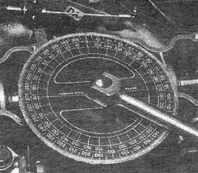
Photo 8.26. A special device used to tighten cylinder head bolts to a specific angle.
27. Install and tension the timing belt (see section 5), and then replace the belt cover.
28. Install the camshaft cover with a new gasket (see photo).
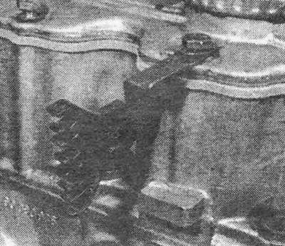
Photo 8.28. Mounting clamps for ignition wires on the camshaft housing cover.
29. Install and tension the generator drive belt (see chapter 2).
30. The remaining operations are performed in reverse order. Upon completion, fill the system with coolant and bleed it (see chapter 2).
31. Start the engine and check for fuel or coolant leaks. After the engine has warmed up to normal operating temperature, check and, if necessary, adjust the idle speed (see chapter 3) and retighten the cylinder head bolts (stage 5).
Visitor comments