
Crankshaft and main bearings
1. Check that the crankcase and crankshaft are immaculately clean and that the lubrication channels are cleaned. If possible, blow out the passages and holes with compressed air and inject clean engine oil through them to make sure they are not clogged.
2. Wipe the crankcase bearing housings and bearing caps clean and install the upper halves of the main bearing shells into the housings.
3. Note that there is a tab at the back of each bearing that must fit into the recess provided for it.
4. In the case of new bearings, wipe off all traces of protective lubricant.
5. The central bearing also controls the axial movement of the crankshaft. Please note that all halves of the liners located in the crankcase have lubrication holes (see photos).
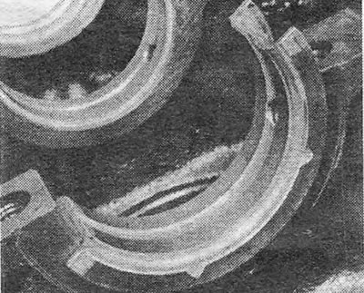
Photo 34.5A. Central main bearing shell. The thrust flanges are visible.
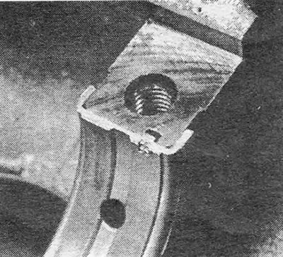
Photo 34.5V. Main bearing shell installation groove.
6. After installing the bearing shells into the crankcase and covers, lubricate them with clean engine oil.
7. Fill the lips of the new crankshaft oil seal with grease and install it on the end of the crankshaft.
8. Carefully install the crankshaft into its place in the crankcase (see photos).
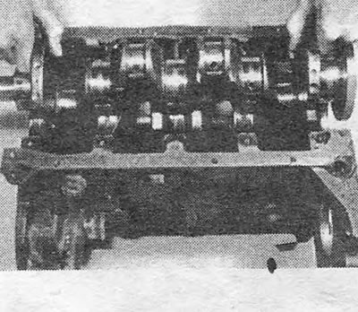
Photo 34.8A. Reinstalling the crankshaft into the crankcase.
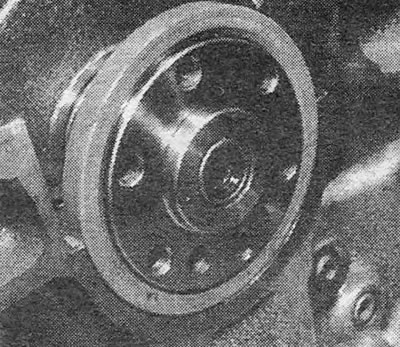
Photo 34.8V. Rear crankshaft oil seal.
9. Lubricate the crankshaft journals and replace the central and intermediate main bearing caps. Tighten the cover bolts to the specified torque (see photos).
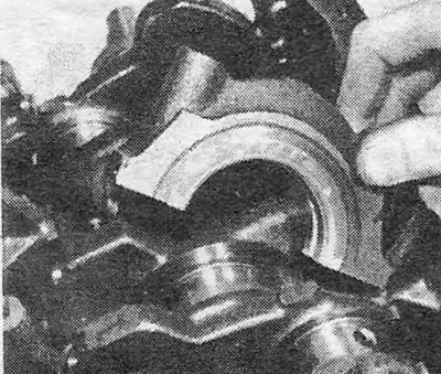
Photo 34.9A. Installing the main bearing cap.
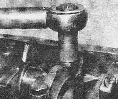
Photo 34.9B. Tightening the main bearing cap bolt.
10. Clean the grooves in the rear main bearing cap from old sealant and coat the inner surfaces of the cap with sealant that meets GM specification 15 04 200/8 983 368*. (This sealant is sold in 200 ml tubes in GM specialty stores). Fill the side grooves in the lid with adhesive-sealant that vulcanizes at room temperature. After installing the cover in place and tightening its bolts, once again inject the adhesive sealant into the side grooves so that you can be sure that they are filled. Wipe off excess sealant (see photos).
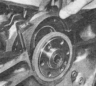
Photo 34.10A. Installing the rear main bearing cap.
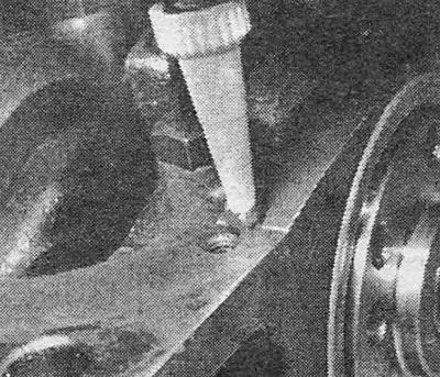
Photo 34.10B. Injecting room temperature curing adhesive into the grooves in the rear main bearing cap.
11. Reinstall the front main bearing cap, lubricate the bolts with sealant and tighten them to the required torque. Make sure that after tightening the bolts, the bearing cap is exactly flush with the end surface of the crankcase.
12. Rotate the crankshaft and check that it rotates freely without jamming or tight spots. Check that the axial movement of the crankshaft does not exceed the specified limits. If necessary, you can adjust the axial movement by selecting other central bearing shells. The axial movement of the crankshaft can be checked using a dial gauge or feeler gauges inserted between the center bearing shell flange and the crankshaft surface. Before starting measurements, check that the crankshaft is moved all the way to one side of the crankcase so that the widest possible gap is obtained at the measurement location (see photo).
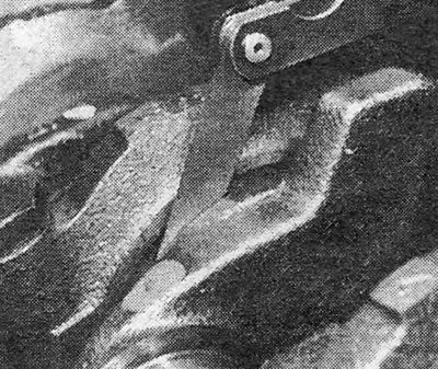
Photo 34.12. Checking the axial movement of the crankshaft using a thickness gauge.
Piston rings
13. Check that the grooves for the rings are well cleaned. The rings are put on the piston through the bottom.
14. To prevent them from sliding into empty grooves when installing the rings, thickness gauge probes or thin steel strips should be placed under them. Installation of the rings is carried out in the reverse order of their removal.
15. When installing piston rings, strictly follow the manufacturer's instructions. There are several types of compression and oil rings, and each type has its own method for proper installation.
16. After installing the rings, check that the compression rings can compress and expand freely in their grooves. Some types of multi-piece oil rings have a tight fit in their grooves and therefore the above does not apply to them. Rotate the rings so that the locks of adjacent rings are spaced apart from each other by approximately 180 degrees. If the oil scraper ring consists of 2 sections, between which a spacer ring is placed, the lock of the upper section should be shifted relative to the lock of the spacer ring by 25-50 mm to the left, and the lock of the lower section by the same distance to the right.
Pistons/rods
17. As stated earlier, disconnecting pistons and connecting rods requires special equipment and must be done by a specialist.
18. Before starting installation, arrange the pistons with connecting rods and bearing caps in the order in which they are installed in the cylinders.
19. Wipe the cylinders and lubricate them with oil. Lubricate the piston rings well.
20. Install the ring compressor onto the first piston so that the base of the compressor rests on the cylinder block. Check that the marks on the connecting rod are facing in the right direction (this is extremely important, because there are no corresponding marks on the piston heads indicating the direction).
22. Using a wooden hammer handle, drive the piston and connecting rod into the cylinder. The compressor will remain standing on the cylinder block.
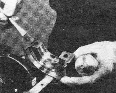
23. Bring the lower head of the connecting rod to the connecting rod journal. Install and lubricate the bearing shells, install the cover and tighten the bolts (see photo).
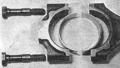
Photo 34.23A. Parts of the lower connecting rod head.
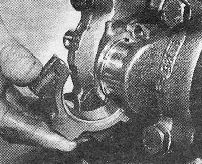
Photo 34.23B. Installing the connecting rod bearing cap.
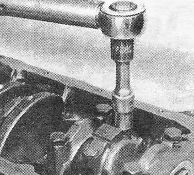
Photo 34.23С. Tightening the connecting rod bearing cap bolt.
Oil pump
24. Before installing the oil pump, care must be taken to ensure that the oil seal lips are not damaged or bent back on the shoulder at the front end of the crankshaft. To do this, lubricate the jaws with grease and wrap the end of the camshaft with adhesive tape so that a smooth cone is formed. Install a new gasket (see photos).
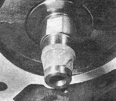
Photo 34.24A. The end of the crankshaft is wrapped to cover the collar.
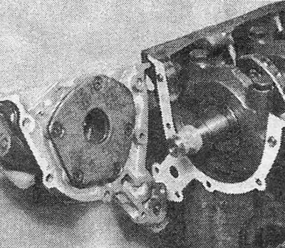
Photo 34.24B. Installing the oil pump and gasket.
25. Reinstall the pump and remove the adhesive tape.
26. Tighten the bolts to the required torque.
27. Reinstall the oil intake pipe and strainer (see photos).
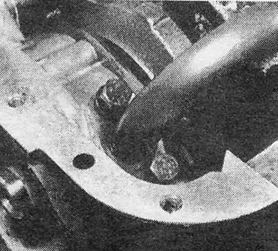
Photo 34.27A. Connecting flange for oil intake pipe.
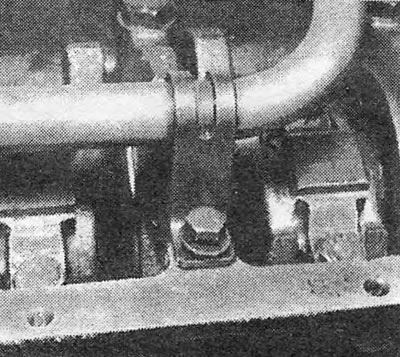
Photo 34.27B. Oil intake pipe support bracket.
28. Replace the tray (see photo).
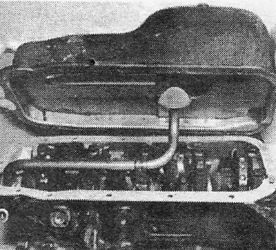
Photo 34.28. Reinstalling the tray with gasket.
29. Install the key on the front end of the crankshaft, turn the engine over and support it on the pallet (see photo).
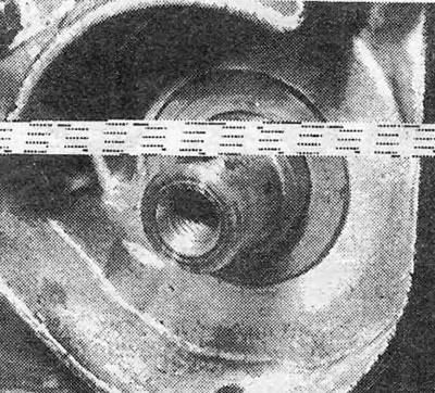
Photo 34.29. Installing a segment key on the crankshaft.
Flywheel
30. Bring the flywheel to the rear mounting flange of the crankshaft and align the holes for the bolts, which are offset so that the flywheel can only be installed in one position (see photo).
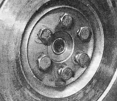
Photo 34.30. Properly installed flywheel.
31. Apply thread locking compound to the bolts, install them in place and tighten them by hand.
Pic. 1.31. Applying sealant to the internal surfaces of the main bearing cap
32. Lock the flywheel ring gear and tighten the bolts to the required torque (see photo).
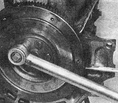
Photo 34.32. Tightening one of the flywheel bolts.
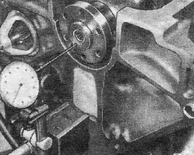
Pic. 1.32. Checking the axial movement of the crankshaft using a dial gauge
Cylinder head and camshaft housing
33. Check that all valves and springs are clean, and that there is no soot or valve grinding paste left in the guide bushings and holes in the cylinder head.
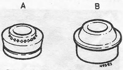
Pic. 1.33. Different types of valve stem seals: A. Early type; B. The last type.
34. Start assembly from one end of the cylinder head as follows.
35. Insert the valve into the guide sleeve, checking that the valve stem is well lubricated. Valves must be installed in the seats to which they were lapped (see photo).
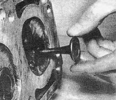
Photo 34.35. Installing the valve in the cylinder head.
36. In the case of an intake valve, install the spring seat; in the case of an exhaust valve, install the valve rotator (see photos).
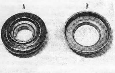
Photo 34.36A. Rotator (A) exhaust valve and spring seat (IN) intake valve.
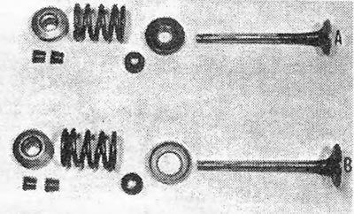
Photo 34.36B. Valve details: A Exhaust valve; B Inlet valve.
37. Holding the valve in place, carefully push the valve stem seal onto the guide sleeve so that the collar on the cap fits into the groove on the sleeve. Do not push the cap further than the groove, as after that he will not be able to perform his functions. Please note that the 1.6 and 1.8 engines have modified valve stem seals. Figure 1.33 shows valve stem seals of the old and new types. New caps can be installed on older engines.
38. Reinstall the valve spring.
39. Reinstall the spring plate (see photo).
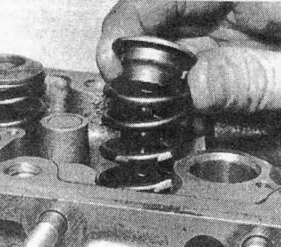
Photo 34.39. Installing the valve spring retainer.
40. Place the end of the spring compressor on the plate and its screw head on the valve head and tighten the screw until the spring is lower than the groove in the valve stem. Apply a little lubricant to the groove.
41. Place the crackers in the groove with the narrow edge towards the spring. Lubrication will keep the crackers in place (see photo).
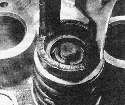
Photo 34.41. Installation of crackers.
42. Slowly release pressure from the spring, making sure that the crackers do not come out of the groove. When the spring is completely released, the upper edges of the crackers should align with each other. Once all the valves are in place, gently tap the top of each spring with a soft-faced hammer to firmly seat the bolts in place.
43. Lubricate the hydraulic tappets and insert them into their channels in the cylinder head (see photo). If you are installing new tappets, you should first immerse them in clean engine oil and manually squeeze them several times to charge them.
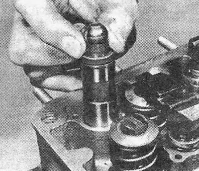
Photo 34.43. Installing a hydraulic pusher into the cylinder head.
44. Reinstall the rockers with thrust pads. Install new spark plugs (see photos).
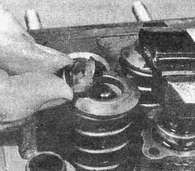
Photo 34.44A. Installation of the thrust pad.
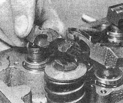
Photo 34.44B. Rocker installation.
45. Install the thermostat with a new sealing ring. Install the thermostat housing cover and tighten the bolts (see photo).
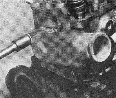
Photo 34.45. Tightening one of the thermostat housing bolts.
46. On 1.3 engines, install the rear camshaft belt guard on the front end of the camshaft cover (see photo).
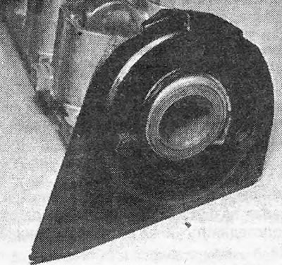
Photo 34.46. Rear camshaft belt guard (engine 1.3).
47. Lubricate the camshaft bearings and carefully insert the camshaft into its crankcase (see photo).
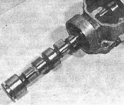
Photo 34.47. Insert camshaft.
48. Install the locking plate with fixing screws and check the axial movement of the camshaft (see photos).
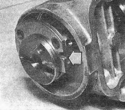
Photo 34.48A. Camshaft lock plate (shown by arrow).
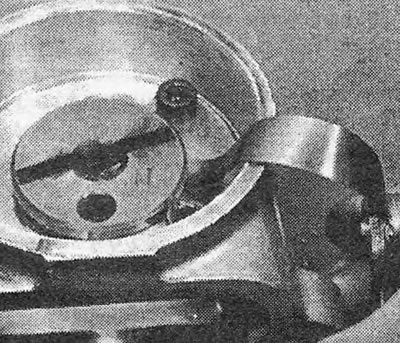
Photo 34.48B. Checking the axial movement of the camshaft.
49. Install a new oil seal in the holder (if it hasn't been done yet) and, holding the camshaft with an open-end wrench, install the camshaft sprocket, secure it with a bolt and tighten the bolt to the required torque (see photo).
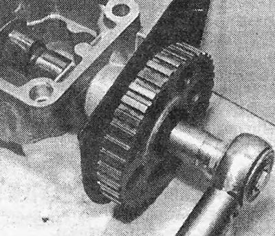
Photo 34.49. Tightening the camshaft sprocket bolt.
50. Thoroughly clean the sealing surfaces of the cylinder head and block.
51. Install a new cylinder head gasket on the block with OBEN lettering facing up (see photo).
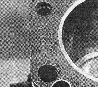
Photo 34.51. Inscription on the top surface of the cylinder head gasket.
52. Install the head on the block so that the dowel pins fit into the holes provided for them (see photo).
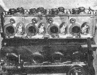
Photo 34.52. Installing the head on the cylinder block.
53. Apply adhesive compound to the sealing flanges of the cylinder head and camshaft housing and install the camshaft housing on the cylinder head (The timing marks on the camshaft sprocket must align) (see photo).
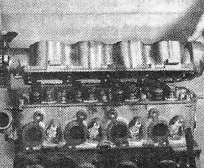
Photo 34.53. Installing the camshaft housing.
54. Reinstall the cylinder head bolts and tighten them in the sequence shown in Fig. 1.3. Bolts are tightened in 5 stages (see Specifications and section 8).
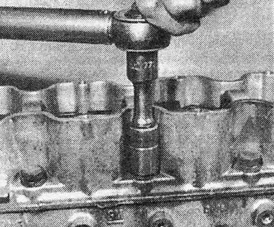
Photo 34.54. Tightening the camshaft housing bolts
55. Install the water pump (see chapter 2) and tighten the bolts securing it by hand (final tightening is done after installing the camshaft belt) (see photo).
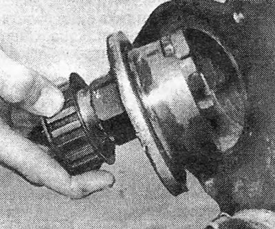
Photo 34.55. Installing a water pump.
56. Secure the rear camshaft belt guard with bolts (see photo).
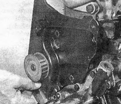
Photo 34.56. Installing the rear camshaft belt guard.
57. Install the sprocket on the front end of the crankshaft so that the raised key on the sprocket fits into the slot on the crankshaft pulley (see photo).
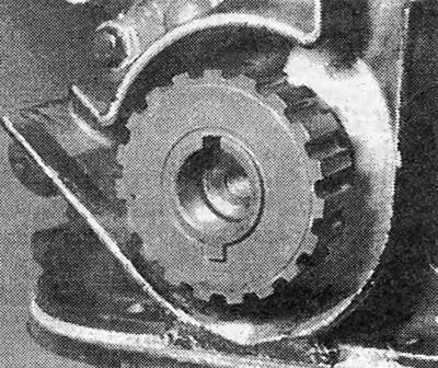
Photo 34.57. Camshaft sprocket.
58. Fix the sprocket with a bolt and tighten it to the required torque (see Specifications).
59. Install and tension the camshaft belt (see section 5).
60. Install the camshaft belt cover. On early models, the upper cover screw can only be tightened after the camshaft cover with a new gasket has been installed (see photos).
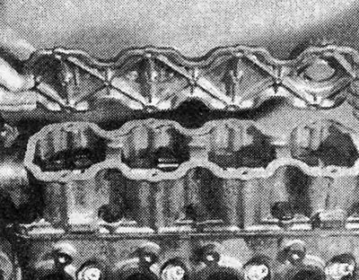
Photo 34.60A. Installing the camshaft housing cover.
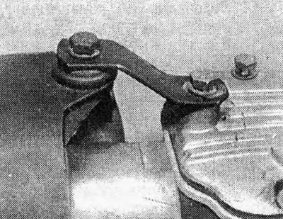
Photo 34.60B. Connecting link between the camshaft belt cover and the camshaft housing cover.
61. Connect the intake and exhaust manifolds with new gaskets and tighten the bolts. Don't forget to secure the engine lifting lugs (see photos).
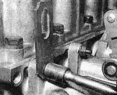
Photo 34.61A. Engine lifting lug, standing on the intake manifold stud.
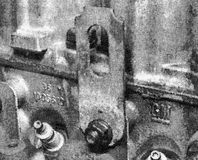
Photo 34.61B. Engine lifting eye, standing on the exhaust manifold stud.
62. Connect the hot air manifold to the exhaust manifold (engines 1.3 and 1.6) (see photo).
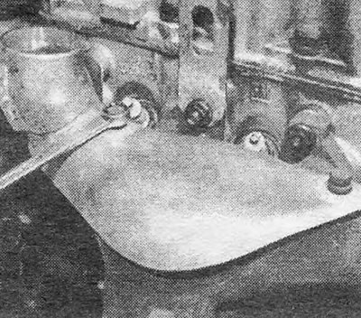
Photo 34.62. Exhaust manifold hot air manifold.
63. Install engine accessories (see relevant chapters). The generator and its drive belt are not installed until the engine is installed on the machine, because otherwise, access to the right rear engine mount will be difficult. The starter is also installed only on an engine already installed on the car.
64. On 1.8 engines, connect the injection system (see chapter 3).
Visitor comments