
Removing
Remove the gearbox from the engine.
Remove the oil dipstick guide tube.
Turn out a bolt.
Remove the heated lambda fuel mixture control sensor.
Disconnect the wiring harness connector.
Release the wiring harness.
Carefully unscrew the lambda sensor using tool KM-6129.
Remove the exhaust manifold shield.
Loosen 2 mounting screws.
Remove the exhaust manifold.
Unscrew 7 fastening nuts.
Take out the seal.
Raise the engine.
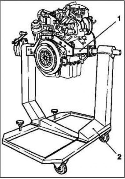
Install on the engine using tool KM-412-18.
Tighten the 4 mounting bolts.
Attach the motor to the KM-412 tool 2.
Tighten 8 threaded connections.
Install tool KM-2358.
Drain the engine oil.
Substitute the collecting tray.
Turn out a carving stopper of a drain aperture.
Remove the oil filter housing cover.
Remove the oil filter insert.
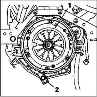
Remove the clutch.
Remove flywheel.
Install the KM-652 tool.
Loosen 6 mounting screws.
Remove the KM-652 tool.
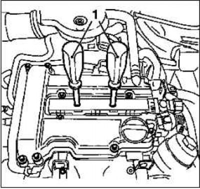
Remove the engine holder on the right 1.
Loosen 3 mounting screws.
Screw in the oil drain plug.
Replace O-ring.
Tighten the bolt to 10 Nm.
Remove the oil sump.
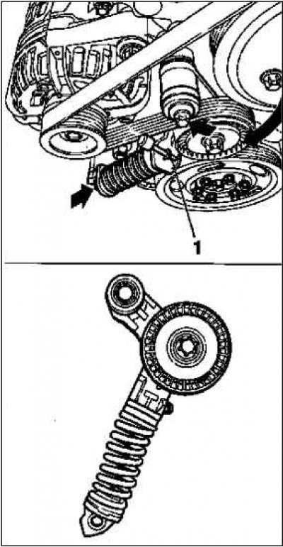
Remove poly V-belt.
Note. Mark the direction of rotation.
Tighten the poly V-belt tensioner in the direction of the arrow.
Insert tool KM-955-2.
Remove the crankshaft poly V-belt from the pulley.
Remove the poly V-belt pulley for the coolant pump.
Loosen 3 mounting screws.
Remove the crankshaft poly V-belt pulley.
Loosen 6 mounting screws.
Hold the crankshaft hub bolt.
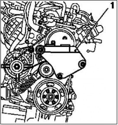
Remove the V-ribbed belt tensioner.
Loosen 2 mounting screws.
Dismantle the engine wiring harnesses.
Unscrew the generator wiring harness.
Loosen 2 nuts.
Loosen the starter wiring harness.
Loosen 2 nuts 1.
Remove the cable ties.
Dismantle the generator.
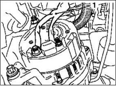
Loosen 2 screw connections.
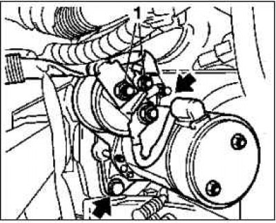
Remove the starter.
Loosen 2 fixing screws (arrows).
Remove the engine control wiring harness.
On the Z 10 XEP engine: remove the fuel distributor pipe cover.
Loosen 2 mounting screws.
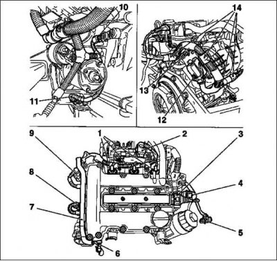
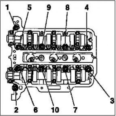
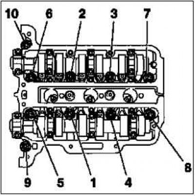
Disconnect the 12 engine management harness connectors.
Oil pressure switch 6, coolant temperature sensor 8, camshaft sensor 9, throttle module 2, engine management controller 12, EGR valve 4, ignition module 3, knock sensor 10, crankshaft sensor 11, fuel injectors 1.
Unscrew the ground wire of the engine control controller 13.
Clear the channel for the wiring harness 7.
Release the wiring harness - 4 holders 14.
Disconnect 3 hoses from the coolant pump.
Disconnect the coolant hose from the exhaust gas recirculation coolant flange.
Release clamp.
Remove coolant pump 1.
Note. When removing, pay attention to the guide bushings.
Substitute the collecting tray.
Remove 9 mounting screws.
Note. Take into account the different lengths of the mounting bolts (arrows - short bolts).
Remove the ignition module.
Remove the ignition module cover by sliding it to the right.
Loosen 2 mounting screws.
Remove the cover using tool KM-6009 1.
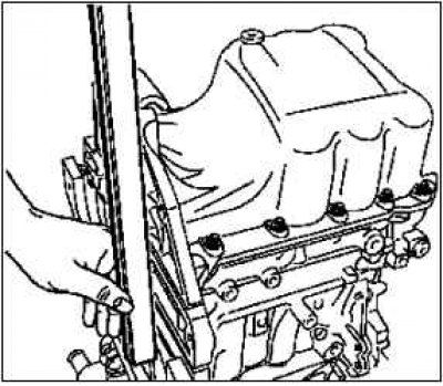
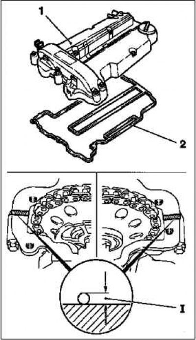
Remove the cylinder head cover.
Remove the crankcase ventilation hose.
Release clamp.
Remove 17 mounting bolts.
Loosen the crankshaft hub bolt 1.
Note. This work will require the participation of two people.
Install and hold the KM-956-1 / KM-956-2 attachments.
Hold KM-956-1 / KM-956-2.
Adjust camshafts.
Using tool KM-956-1 / KM-956-2, turn the crankshaft evenly in the direction of engine rotation until tool KM-953 1 hits the camshaft groove as far as it will go.
Remove the crankshaft hub.
Note. Observe the mounting position of the hub.
Turn out a bolt.
Remove the hub using tools KM-956-1 / KM-956-2.
Remove the oil pan.
Rotate the motor 180°.
Remove 14 mounting bolts.
Remove the oil pan seal.
Remove the timing case.
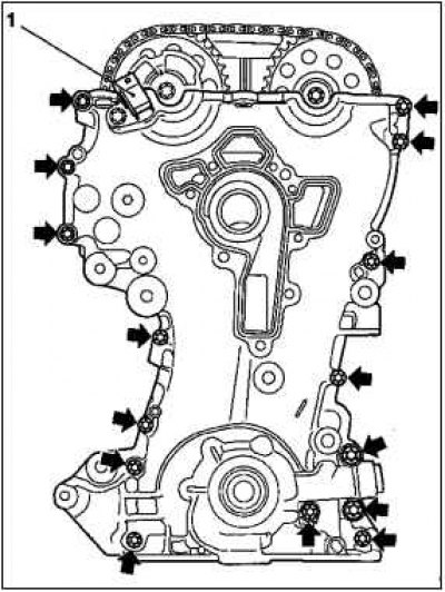
Rotate the motor 90°.
Remove 15 mounting bolts (arrows).
Consider the length of the mounting bolts.
Do not damage the camshaft sensor 1.
Lift and remove the timing case O-ring.
Note. Do not damage the sealing surface.
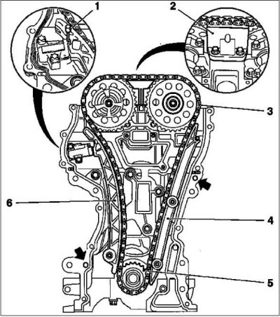
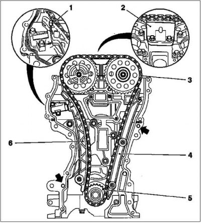
Remove the chain drive.
Loosen the camshaft drive gear bolts.
Hold the camshafts by the hexagon.
Lock chain tensioner 1.
Insert tool KM-955-1.
Remove damper bar 3, guide bar 5, tensioner slide 7 and camshaft drive gears.
Remove the camshaft timing chain 4 with the drive wheel 6. Remove the timing case seal.
Remove the cylinder head.
Rotate the motor 90°.
Remove tool KM-953.
Loosen 10 mounting screws.
Note. Loosen the cylinder head studs in the following order:
Note. – release hairpins of a head of cylinders (90°);
Note. – release hairpins of a head of cylinders (180°);
Note. – Take out hairpins of a head of cylinders.
Insert the cylinder head into wooden blocks.
Remove the cylinder head seal.
Remove the oil filter housing.
Loosen 3 mounting screws.
Remove the knock sensor.
Turn out a bolt.
Remove the oil deflector.
Rotate the motor 180°.
Loosen 6 mounting screws.
Remove the crankshaft position sensor.
Turn out a bolt.
Remove the cylinder block.
Install tool KM-2358.
Hang the engine on a crane.
Remove tool KM-412-18.
Install the cylinder block.
Install tool KM-412-18 on the engine. Tighten the 4 mounting bolts.
Remove tool KM-2358.
Using the KM-427 tool, press 6 guide sleeves into the cylinder block.
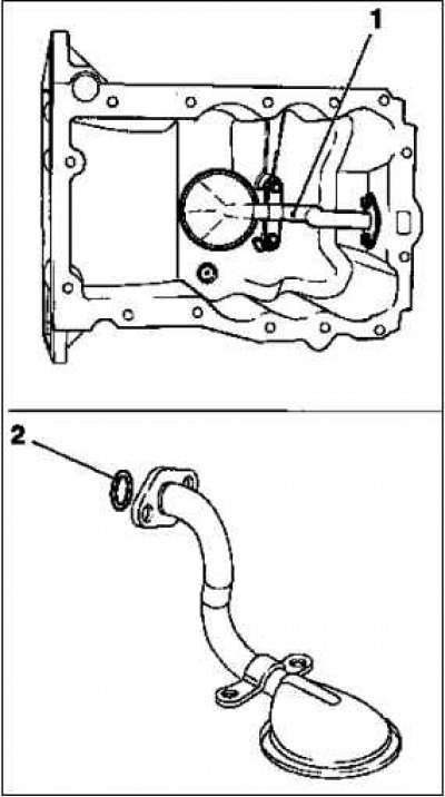
Dismantle the suction oil line 1.
Loosen 4 mounting screws.
Remove sealing ring 2.
Clean the sealing surfaces of the cylinder block and cylinder head, cylinder head cover, oil filter housing, crankshaft bearing, timing housing, oil pan, water pump and exhaust manifold.
Engine mounting
Inspect the components of the power unit.
Note. If necessary, check and process the cylinder head, remove all externally installed parts from the cylinder head: cylinder block, cylinder head, cylinder head cover, oil filter housing, crankshaft support, chain drive, timing case, oil pan, coolant pump, exhaust manifold.
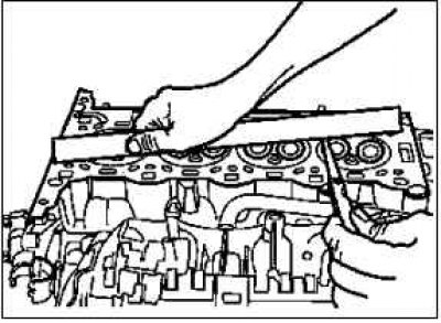
Using a straightedge and feeler gauge, check the cylinder head for straightness.
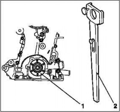
Stop the crankshaft.
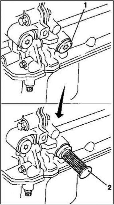
Remove screw plug 1.
Insert tool KM-952 2 in its place.
Rotate the crankshaft evenly until the tool engages.
Install the oil deflector.
Tighten 6 mounting bolts to 8 Nm.
Install the oil filter housing.
Rotate the motor 180°.
Replace seal.
Tighten the 3 mounting bolts with a tightening torque of 20 Nm.
Replace oil filter insert.
Install the oil filter housing cover.
Replace O-ring.
Tighten the cover bolts to 10 Nm.
Adjust camshafts.
Insert tool KM-953.
Turn the camshafts by the hexagon.
Remove tool KM-953.
Install the cylinder head.
Replace seal.
Note. Marking «OPEN/TOP» should point up.
Note. Replace the cylinder head bolts.
Align the cylinder head with the cylinder block using a straight edge.
Tighten 10 mounting bolts to 25 Nm. + 60°+ 60°+60°.
Note. Follow the bolt tightening sequence.
Install the camshaft timing chain.
Install the KM-953 tool.
Replace the timing case seal.
Note. Check for correct fit (arrows).
Replace bolts.
Move drive wheel 5.
Fit the exhaust camshaft gear. Screw in the bolt.
Install the camshaft timing chain 3.
Insert the intake camshaft gear with the phase sensor disk into the camshaft drive chain, screw in the bolt.
Note. The phase encoder disk must be turned by hand.
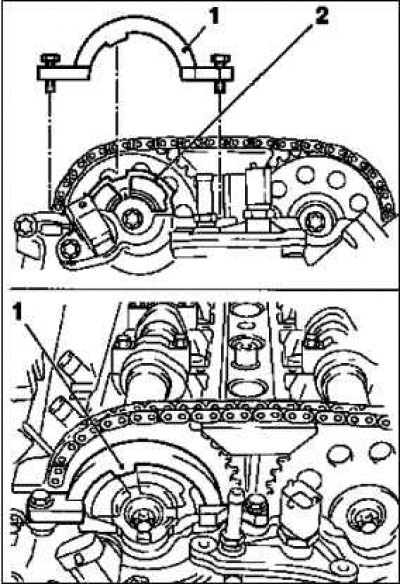
Install the camshaft timing chain tensioner 6.
Tighten the bolt with a tightening torque of 20 Nm.
Note. Make sure the camshaft timing chain is seated correctly.
Install the camshaft timing chain guide groove 4.
Tighten 2 mounting bolts with a torque of 8 Nm.
Note. Make sure the camshaft timing chain is seated correctly.
Install the camshaft guide rail 2.
Tighten 2 mounting bolts with a torque of 8 Nm.
Loosen the chain tensioner.
Remove tool KM-9551.
When replacing parts, consider the different design options. Make sure the part numbers are correct.
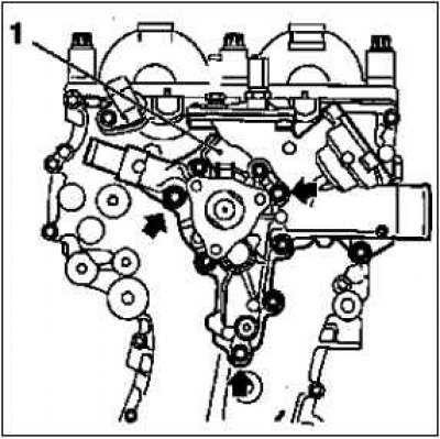
Install the coolant pump.
Note. Make sure the guide bushings fit correctly (arrows).
Consolidation 1 replace.
Fix the pump with the short fixing bolts 2.
Tighten 3 mounting bolts 8 Nm.
Remove the coolant pipe by unscrewing the 3 mounting bolts.
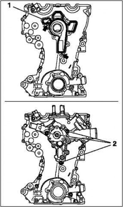
Install the timing case.
Screw in the bolts.
Note. Follow the tightening sequence
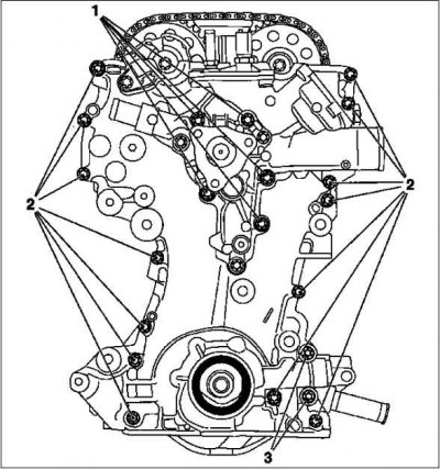
Tighten 5 mounting bolts (M6) torque 18 Nm.
Tighten 14 mounting bolts (M6) torque 28 Nm.
Tighten the 2 mounting bolts (M10) 3 torque 35 Nm.
Install the coolant pipe.
Check and clean the sealing surfaces.
Replace O-ring.
Tighten 3 mounting bolts to 8 Nm.
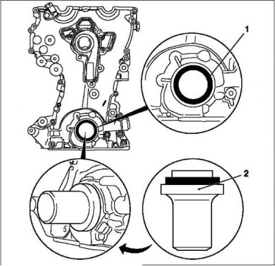
Replace the front crankshaft seal 1.
Lubricate the sealing lips with silicone grease (white).
Install tool KM-960 2 and press in the crankshaft O-ring.
Remove tools KM-952, KM-953.
Note. Locking tools must not be used for holding.
Install the crankshaft hub.
Observe the installation position of the crankshaft hub 2, the mark must point upwards.
Replace hub bolt.
Hold the hub with KM-956-1/KM-956-2.
Tighten the bolt to 150 Nm. +45°.
Remove tools KM-956-1/KM-956-2.
Install the crankshaft poly V-belt pulley 1.
Tighten 6 mounting bolts to 8 Nm.
Hold the crankshaft hub bolt.
Insert tool KM-952.
Insert tool KM-953 into the groove of the camshafts.
Install tool KM-954 1.
Rotate the phase sensor disk 2 until you can install the KM-954 tool on the timing case.
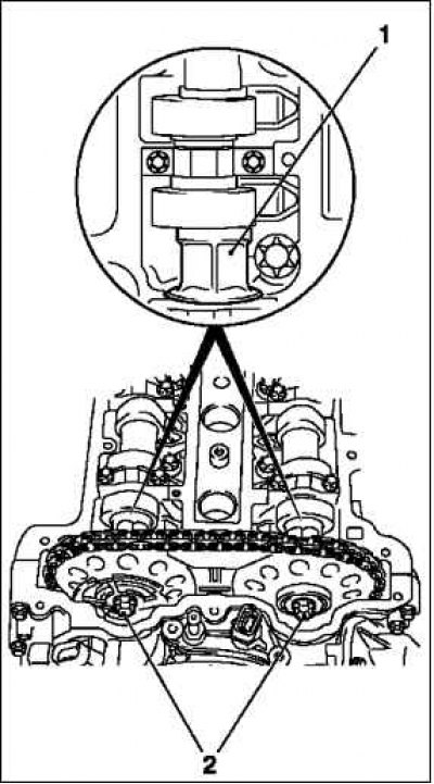
Attach the camshaft drive gears.
Note. Tighten the drive gears of the camshafts and the phase sensor disk with a torque of 10 Nm.
Tighten 2 mounting bolts to 210 Nm.
Note. Tighten the intake camshaft drive gear bolt first.
Support the camshafts by the hexagon 1.
Take out the fixing tools KM-952, KM-953, KM-954.
Tighten the camshaft drive gears.
Tighten the 2 mounting bolts to 50 Nm + 60°.
Note. Tighten the intake camshaft drive gear bolt first.
Note. Hold the camshafts by the hexagon.
Check the valve timing.
Install the oil pan.
Tighten 14 mounting bolts to 10 Nm.
Install the crankshaft support screw plug.
Replace O-ring.
Tighten the fastening bolt to 50 Nm.
Install the knock sensor.
Tighten the mounting bolt with a tightening torque of 20 Nm.
Install the crankshaft position sensor.
Replace O-ring.
Tighten the fastening bolt to 8 Nm.
Install cylinder head cover 1.
Rotate the motor 180°.
Replace seal 2, O-ring.
Apply sealant (distance 1–2 mm).
Note. Complete installation work within 10 minutes.
Tighten 17 mounting bolts to 8 Nm.
Install the crankcase ventilation hose.
Fasten the clamp.
Install the ignition module.
Tighten 2 mounting bolts with a torque of 8 Nm.
Install coolant hoses.
Attach the clamps to the coolant pump and the EGR valve.
Install the engine control harness.
Route the wiring harness.
Connect the 13 wire harness connectors.
Connect the ground wire of the engine control unit.
Tighten the fastening nut.
Attach the wire harness channel.
Fasten the wiring harness.
On the Z 10 XEP engine: install the fuel distributor pipe shroud.
Tighten the 2 mounting bolts.
Install starter.
Rotate the motor 90°.
Tighten 2 mounting bolts to 25 Nm.
Install the generator.
Tighten 2 screw connections to 35 Nm.
Install the engine wiring harness.
Rotate the motor 90°.
Attach the alternator and starter harnesses and tighten the 4 mounting nuts.
Install the V-ribbed belt tensioner.
Rotate the motor 180°.
Bolt (M8) tighten with a tightening torque of 20 Nm.
Bolt (M10) tighten with a tightening torque of 55 Nm.
Install the poly V-belt pulley for the coolant pump.
Tighten the 6 mounting bolts with a tightening torque of 20 Nm.
Install poly V-belt.
Note. Observe direction of rotation and installation position.
Loosen the tension of the V-ribbed belt tensioner.
Remove tool KM-955-2.
Install the engine holder on the right.
Tighten 2 mounting bolts to 60 Nm.
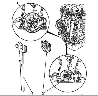
Install the flywheel.
Clean 6 threaded connections in the crankshaft.
Replace mounting bolts.
Tighten 6 mounting bolts to 35 Nm. +60°.
Lock the flywheel with tool KM-652.
Install the clutch.
Fill with engine oil.
Check and, if necessary, correct the engine oil level.
Disconnect the engine from the KM-412 tool.
Unscrew 8 threaded connections.
Remove tool KM-412-18.
Loosen 4 mounting screws.
Install the exhaust manifold.
Replace seal.
Replace nuts.
Tighten the 7 fastening nuts with a tightening torque of 20 Nm.
Install the exhaust manifold shield.
Tighten 2 mounting bolts to 8 Nm.
Install a heated lambda fuel mixture control sensor.
Apply mounting paste to the threads (white).
Tighten the lambda sensor to 40 Nm.
Connect the wire harness connector.
Fasten the wiring harness.
Install the dipstick guide tube.
Replace 2 O-rings.
Tighten the bolt to 8 Nm.
Install the gearbox on the engine.
Visitor comments