
Note. From model year 04, KM-6394 must be used instead of KM-6169-1.
Removing
Open the hood.
Disconnect the battery terminals.
Note. On vehicles from model year 04 with ESP, each time the battery is disconnected, the steering angle sensor loses its basic setting. It needs to be recalibrated.
Disconnect the ground wire.
Drain the coolant.
Note. On model variant «ECO» remove the engine compartment cover at the bottom.
Substitute the collecting tray.
Open the drain plug (arrow).
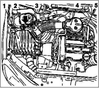
Remove the air filter housing 1.
Disconnect the 2 harness connectors, hot film mass air flow meter 3 and tank vent valve 2.
Release the tank vent valve.
Dismantle the suction pipe 4.
Loosen 2 nuts.
Dismantle the crankcase ventilation hose 5.
On Z10XEP engines: remove the air intake hose.
Release clamp.
Remove the bolt (arrow).
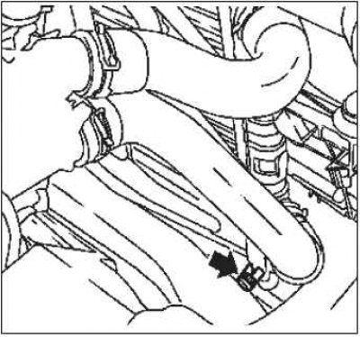
Remove the throttle body heating hose 1.
Release clamp.
Remove the hot water supply hose 6 from the coolant pump.
Release clamp.
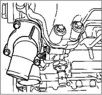
Remove the engine control wiring harness.
Disconnect the 3 harness connectors, oil pressure switch 3, coolant temperature sensor 4, camshaft sensor 5.
Clear the channel for the wiring harness 2.
Set the wiring harness aside.
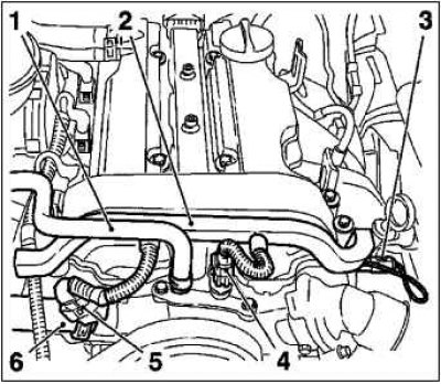
Remove the radiator hose at the top 1.
Loosen 2 clamps.
Disconnect the radiator hose at the bottom 2 from the coolant pump.
Release clamp.
Remove the ignition module.
Remove the ignition module cover.
Move it to the right.
Disconnect the wiring harness connector.
Loosen 2 mounting screws.
Remove with tool KM-6009.
Note. Do not twist the position of the cover.
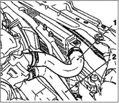
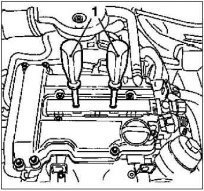
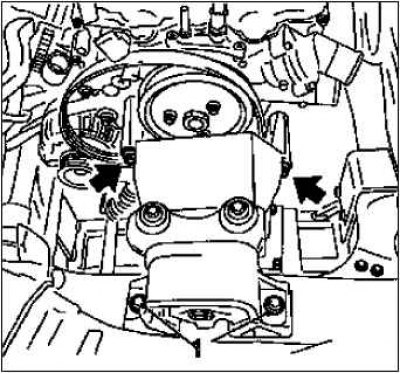
Remove the cylinder head cover.
Remove the crankcase ventilation hose.
Release clamp.
Remove 13 mounting bolts.
Release the front wheel on the right.
Loosen 4 mounting screws.
Raise the vehicle.
Remove the front wheel on the right.
Loosen 4 mounting screws.
Raise the vehicle.
Remove the V-ribbed belt cover.
Note. On model variant «ECO» remove the engine compartment cover at the bottom 1.
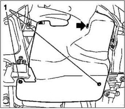
Remove 3 fixing screws 1.
Remove the clip (arrow).
Close the coolant drain plug.
Drain the engine oil.
Substitute another collecting tray.
Unscrew the drain plug.
Note. Bends of the flexible tube even by 5-10 degrees in relation to the intended mounting position can lead to damage to the flexible hose and its subsequent failure.
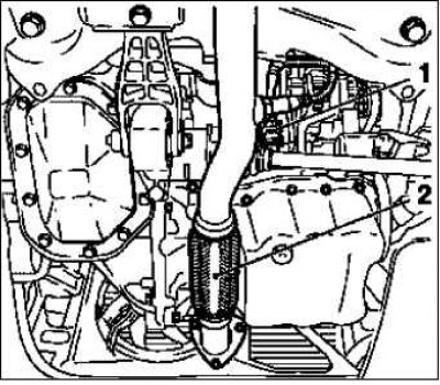
Release the exhaust system.
Note. When removing the middle silencer, catalytic converter, exhaust manifold or exhaust manifold with catalytic converter, the part of the exhaust system remaining in the vehicle must be secured against uncontrolled sagging. To this end, the part of the exhaust system with the flexible pipe in it can be fixed by suitable means, for example with a wire, on the running gear.
Disconnect the catalytic converter 1 lambda sensor harness connector.
Release 2 damping baffles (arrows).
Unscrew the exhaust pipe from the front 2.
Loosen 3 nuts.
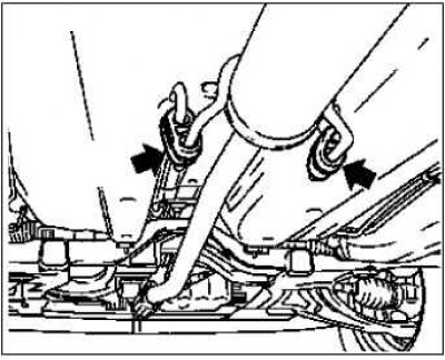
Connect the exhaust pipe from the front to the front axle housing on the left.
Tighten the engine oil drain plug to 10 Nm.
Replace O-ring.
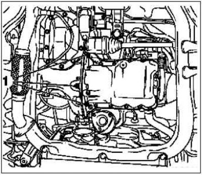
Remove the alternator wiring harness 1.
Loosen 2 nuts.
Remove the cable ties.
Remove poly V-belt.
Using tool KM-6131, tension the poly V-belt tensioner in the direction of the arrow.
Insert tool KM-6130.
Remove the V-ribbed belt tensioner.
Note. Care must be taken to properly support the V-ribbed belt tensioner (arrow pointing up). If this cannot be ensured, the air must be bled from the V-ribbed belt tensioner. To do this, you need to complete at least 5 moves (pull-press), and the loading rate should remain constant, and the loading should be carried out uniformly. Do not damage the tension element.
Tension the polyine belt tensioner with tool KM-6131.
Take out the KM-6130 tool.
Loosen the tension of the V-ribbed belt tensioner.
Loosen the 2 fixing screws 1.
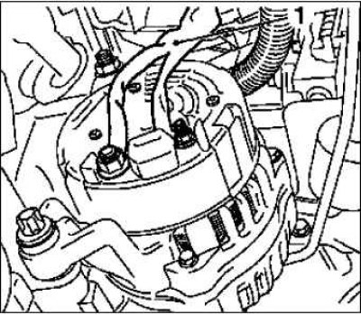
Dismantle the generator.
Unscrew 2 screw connections 1.
Remove the oil pan.
Unscrew the 3 mounting bolts 1 on the gearbox.
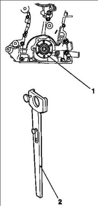
On the crankshaft support, unscrew the 14 mounting bolts.
Install tool KM-6169-2 on the gearbox.
Tighten 2 mounting bolts to 95 Nm.
Install tool KM-61691.
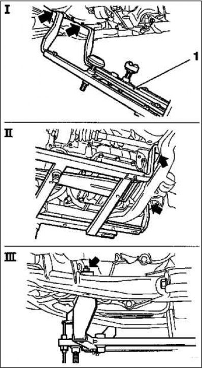
KM-6169 fit on the left side of the front axle housing (arrows, fig. I).
Note. The guide pin must be located in the hole in the front axle housing.
Install both holders on the right on the front axle housing (arrows, fig. II).
Note. The guide pin must be located in the hole in the front axle housing (arrow, fig. III).
Tighten the 8 mounting bolts.
Install the support on the KM-6169 tool.
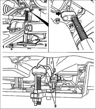
Install mount 2 for the support.
Tighten nut 1.
Adjust the supports.
On the gearbox side, turn the spindles in such a way that the fasteners 3 on the guide pins fit without play.
From the control side of the engine, insert the support trunnion into the hole in the cylinder block without play (arrow).
Tighten nut 1.
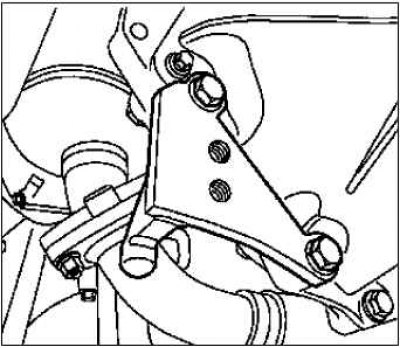
Unscrew the engine holder on the right.
Loosen bolt 1 at the bottom.
Lower the car.
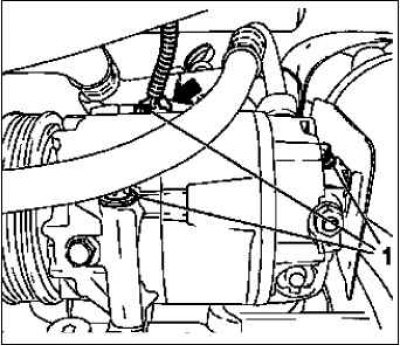
Remove the compressor.
Note. The air conditioning system remains closed.
Disconnect the harness connector (arrow).
Remove 3 fixing screws 1.
Set the compressor aside.
Lower the car.
Remove the engine holder on the right.
Release the damping block of the engine.
Loosen the 2 fixing screws 1.
Loosen 2 fixing screws (arrows).
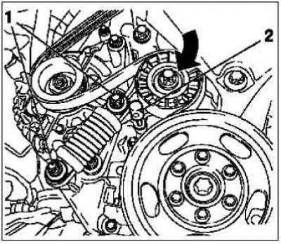
Remove the poly V-belt pulley for the coolant pump.
Loosen 3 mounting screws.
Remove the V-ribbed belt tensioner.
Turn out a bolt.
Remove the coolant pipe.
Loosen 3 mounting screws.
Set the ignition TDC position of cylinder 1.
Remove the crankshaft support screw plug.
Insert tool KM-952.
Note. The mark on the crankshaft pulley 4 must be in line with the boss 3 on the timing case.
Rotate the crankshaft evenly until the KM-952 tool is engaged.
Insert tool KM-953.
Note. KM-953 must enter the groove of the camshafts.
Remove tool KM-953.
Raise the vehicle.
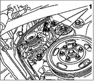
Remove the crankshaft poly V-belt pulley 1.
Loosen 6 mounting screws.
Hold the crankshaft hub bolt.
Loosen the crankshaft hub bolt.
Take out the KM-952 tool.
Install tool KM-956-1/ KM-956-2 3.
Hold attachments KM-956-1/ KM-956-2.
Remove the crankshaft hub 2.
Note. Observe the installation position.
Insert tool KM-952.
Turn out a bolt.
Take it out using tools KM-956-1 / KM-956-2.
Release the timing case from below.
Note. Take into account the different lengths of the mounting bolts.
Loosen 2 fixing screws 3 (M10).
Loosen 14 mounting screws (M6) (arrows).
Lower the car.
Remove the coolant pump.
Note. When removing, pay attention to the guide bushings.
Substitute another collecting tray.
Loosen the 4 fixing screws 2.
Note. Take into account the different lengths of the mounting bolts.
Dismantle the timing case.
Loosen the 4 fixing screws 1.
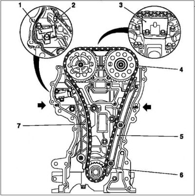
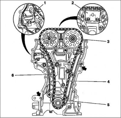
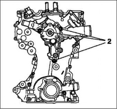
Remove the chain drive.
Loosen the 2 camshaft gear mounting bolts.
Hold the camshafts by the hexagon.
Lock chain tensioner 1.
Insert tool KM-955-1.
Remove damper bar 3, guide bar 5, tension slide 7, camshaft drive gears.
Remove the camshaft drive chain 4 with drive wheel 6.
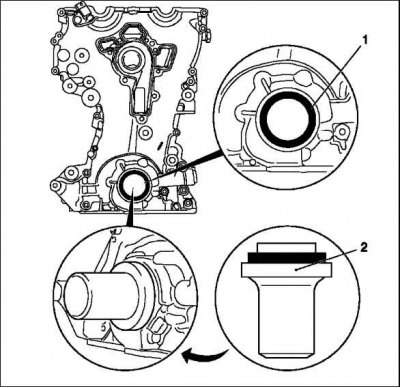
Remove the timing case seal.
Remove the crankshaft seal from the front.
Pry and remove the O-ring.
Note. Do not damage the sealing surface.
Installation
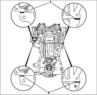
Clean the sealing surfaces of the timing case, cylinder block, cylinder head, crankshaft support, oil pan, cylinder head cover, coolant pump, thermostat housing.
If present, remove sealant from cylinder head seal area.
Examine the nodes.
Note. If necessary, check and process the cylinder head, remove all externally installed parts from the cylinder head: chain drive, timing case, cylinder block, cylinder head, crankshaft support, oil pan, cylinder head cover, coolant pump, thermostat housing.
When replacing parts, consider the different design options. Make sure the part numbers and catalog are correct.
Replace the front crankshaft seal 1.
Lubricate the sealing lips with silicone grease (white).
Slide onto KM-960 fixtures.
Using tool KM-960, drive in flush.
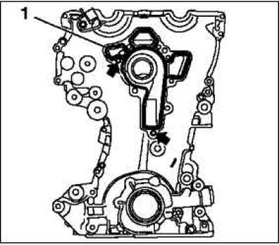
Replace the timing case seal.
Apply silicone sealant to the joint between the cylinder block and the crankshaft bearing.
Note. Complete installation work within 10 minutes.
Peel off the protruding elastomer of cylinder head seal 1 and replace it with a 2 mm thick strip of silicone sealant.
Note. If there is no protruding elastomer, a bead of silicone sealant can be applied immediately.
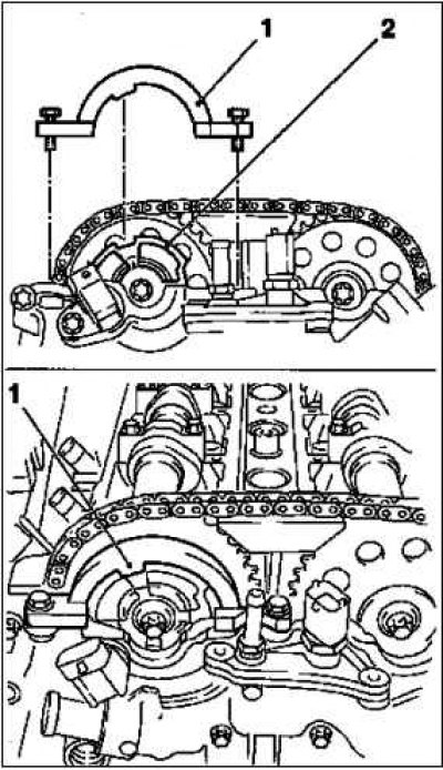
Install the camshaft timing chain.
Note. Make sure the guide bushings fit correctly (arrows).
Install the KM-953 tool.
Bolts replace.
Move drive wheel 5.
Fit the exhaust camshaft gear.
Screw in the bolt.
Install the camshaft timing chain 3.
Insert the intake camshaft gear with phase sensor disk into the camshaft timing chain.
Screw in the bolt.
Note. The phase encoder disk must be turned by hand.
Install the camshaft timing chain tensioner 6.
Tighten the bolt and tighten with a tightening torque of 20 Nm.
Note. Make sure the camshaft timing chain is seated correctly.
Install the camshaft timing chain guide groove 4.
Note. Make sure the camshaft timing chain is seated correctly.
Tighten the bolt 8 Nm.
Install the camshaft guide rail 2.
Tighten 2 mounting bolts with a torque of 8 Nm.
Remove tool KM-955-1.
Install the coolant pump.
Note. Make sure the guide bushings fit correctly (arrows)
Consolidation 1 replace.
Install with short mounting bolts.
Tighten 3 mounting bolts 8 Nm.
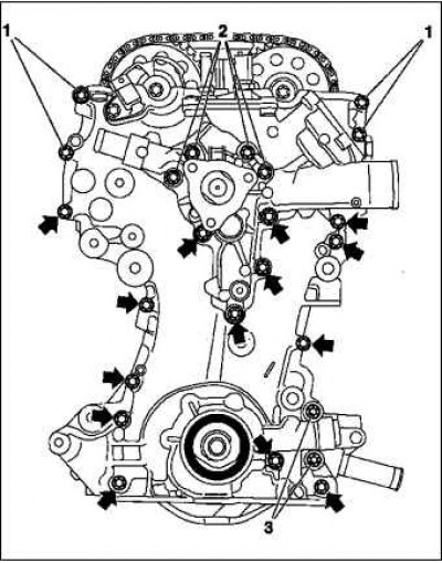
Install the timing case.
Note. Follow the tightening sequence.
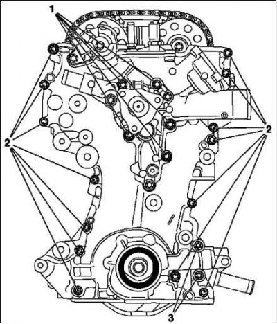
Tighten the 21 mounting bolts.
Tighten 5 mounting bolts 1 (M6) 8 Nm.
Tighten 14 mounting bolts 2 (M6) 8 Nm.
Tighten the 2 mounting bolts 3 (M10) 35 Nm.
Install the coolant pipe.
Replace pipe seal.
Tighten 3 mounting bolts to 8 Nm.
Raise the vehicle.
Take out the KM-952 tool.
Note. Locking tools must not be used for holding.
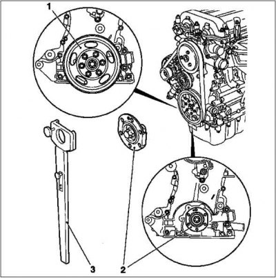
Install the crankshaft hub.
Note. Observe the installation position of the crankshaft hub - the mark must point upwards.
Bolt replace.
Tighten the crankshaft hub bolt.
Note. This procedure will require the work of two people.
Hold the hubs with KM-956-1/KM-956-2.
Tighten the bolt to 150 Nm. +45°.
Remove tools KM-956-1/KM-956-2.
Install the crankshaft poly V-belt pulley.
Tighten 6 mounting bolts to 8 Nm.
Hold the crankshaft hub bolt.
Insert tool KM-952.
Lower the car.
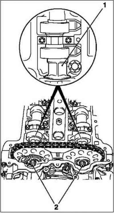
Install tool KM-9541.
Rotate the phase sensor disk 2 until you can install the KM-954 tool on the timing case.
Attach the camshaft drive gears.
Note. Tighten the intake camshaft drive gear bolt first.
Tighten 2 mounting bolts to 210 Nm.
Note. Tighten the drive gears of the camshafts and the phase sensor disk with a torque of 10 Nm.
Support the camshafts by the hexagon 1.
Take out the fixing tools.
Note. Locking tools must not be used for holding.
Tighten the camshaft drive gears.
Note. This procedure will require the work of two people.
Tighten the bolts to a torque of 50 Nm +60°.
Note. Tighten the intake camshaft drive gear bolt first.
Hold the camshafts by the hexagon.
Rotate the crankshaft (720°).
Install tools KM-952, KM-953, KM-954.
Take out the fixing tools KM-952, KM-953, KM-954.
Raise the vehicle.
Install the crankshaft support screw plug.
Replace O-ring.
Tighten the bolt 50 Nm.
On the model «ECO» put the engine cover down.
Lower the car.
Clean the sealing surfaces of the cylinder head, cylinder head covers.
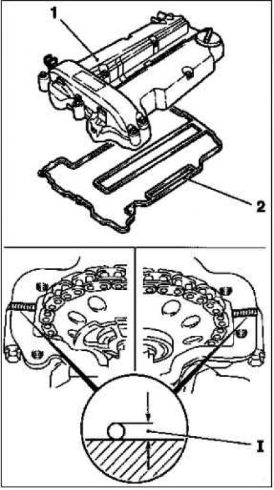
Install cylinder head cover 1.
Replace seal 2 and o-ring.
Apply sealant (distance 1–2 mm).
Note. Installation work must be completed within 10 minutes.
Tighten 13 mounting bolts to 8 Nm.
Install 2 crankcase ventilation hoses.
Install the ignition module.
Unscrew 2 pcs. KM-6009.
Tighten 2 mounting bolts with a torque of 8 Nm.
Install the engine control harness.
Route the wiring harness.
Attach the wire harness channel.
Connect the 4 wire harness connectors.
Connect the battery terminals.
Program the volatile memory.
Close the hood.
Visitor comments