


Removal
Caution: All brake shoes must be replaced at the same time, even if the lining of only one of them has reached the wear limit! Use only shoes approved for use by the manufacturer! Never use gasoline or petroleum-based solvents to clean brake system components - use only branded cleaning agents or methyl alcohol!
Caution: When performing work, observe the safety precautions specified in Section 1!
Note: It is correct to disassemble the brake mechanisms one by one - the assembled mechanism can be used as a sample when assembling the dismantled one, if necessary. If both mechanisms are disassembled and the same brake shoes are to be reinstalled, their installation locations must be marked when removing. It is not allowed to switch shoes from the right wheel to the left!
Note: It is advisable to simultaneously replace the brake shoes with their tension and guide springs, which, as a result of loads, stretch/sag over time, ceasing to develop the required force, which leads to the brakes seizing and accelerated wear of the drums.
1. Support the front wheels with wheel chocks, remove both rear wheels and place the rear of the vehicle on stands.
2. On Corsa C models, use a screwdriver to remove the protective cap from the wheel hub and loosen the hub nut (see accompanying illustration), please comply with all requirements specified in the relevant section Chapters 8.
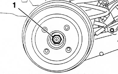
10.2. Rear wheel hub nut (1) (corsa C models, drum brake mechanism)
Note: The protective cap is damaged when removed and must be replaced when installed.
3. On Corsa Combo models, remove the brake drum locking screw (see accompanying illustration).
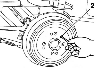
10.3. Brake drum locking screw (2) (corsa Combo models)
4. Release the parking brake lever, if necessary, loosen the parking brake cable (see Section 17).
5. Remove the brake drum from the axle. If any of the discs have become stuck to the wheel hub as a result of long-term use, use a plastic hammer and knock the disc off with light blows.
6. If these attempts are unsuccessful, insert a screwdriver through the hole on the back of the brake shield (see accompanying illustration) and press the parking brake lever outward, while the spring moves the brake shoes away from the drum.
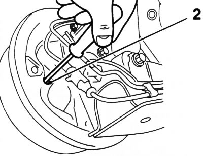
10.6. Hole (2) for releasing the parking brake lever
7. Using the special Hazet-797 tool, disconnect the upper tension spring of the brake mechanism and use a screwdriver to separate the mounting bracket from the front brake shoe (see accompanying illustration).
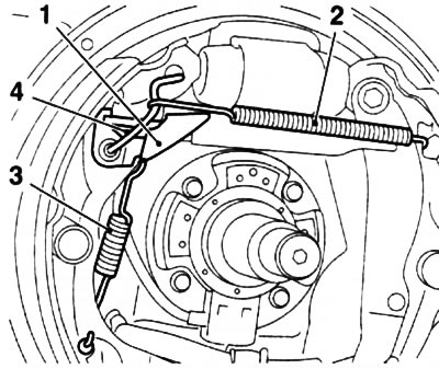
10.7. Tension (2) and return (3) springs of the drum brake mechanism: 1. Adjusting lever; 4. Mounting bracket
8. Remove the adjusting lever from the brake shoe and disconnect the return spring from it (see illustration 10.7).
9. Slightly spread the brake shoes and remove the adjusting expansion bar installed between them (see accompanying illustration).
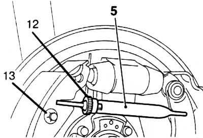
10.9. Adjusting expansion bar (5): 12. Adjusting gear; 13. Disc spring of the adjusting lever
10. Using a special device KM-346 or Hazet-4963-1, press down the front brake shoe pressure spring plate (see accompanying illustration). Overcoming the force of the spring, turn the plate and release it from the retainer, while holding the retainer from behind. Remove the plate and spring, remove the retainer. Repeat this operation for the rear shoe.
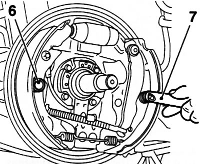
10.10. Press down the brake shoe pressure spring (6) using the KM-346 tool (7)
11. Remove the front brake shoe and disconnect the lower return spring (see accompanying illustration).
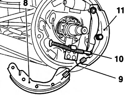
10.11. Removing the front (8) and rear (11) brake shoe: 9. Lower tension spring; 10. Parking brake drive cable
12. Remove the rear brake shoe and disconnect the drive cable from the parking brake actuator lever (see illustration 10.11).
13. To avoid squeezing out the pistons of the wheel brake cylinder, it is necessary to press the pistons using a special spring clamp or belt.
Warning: Do not press the brake pedal with the brake pads removed! If the pistons have been squeezed out of the brake cylinder, remove the cylinder and take it to a car service workshop for assembly or replace it. Be careful not to damage the brake cylinder seals!
Examination
14. Clean all brake components, taking precautions (see Section 1).
15. If traces of brake fluid leakage are found on the wheel brake cylinder cuffs, replace the corresponding cuff. When installing new cuffs, (see accompanying illustration) make sure that the pistons are not pushed out of the cylinder.
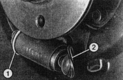
10.15. Wheel brake cylinder seals (1 and 2) - the illustration shows a different Opel model
16. Check the condition of the inner working surface of the drum; if necessary, have the drums machined.
Note: Both drums must be resurfaced to the same depth. The authors of this Manual recommend replacing the brake shoes after resurfacing the drums.
17. If the furrows are too deep or the maximum permissible value of its diameter is exceeded (see Specifications to Chapter 1) replace the drums of both brake mechanisms.
18. Small traces of corrosion are removed using fine-grained sandpaper. Contact points (see accompanying illustration) clean the brake shoes and the rear shield of the brake mechanism with a metal brush and lubricate with a thin layer of special paste (for example, Liqui Moly) to prevent brake squeal.
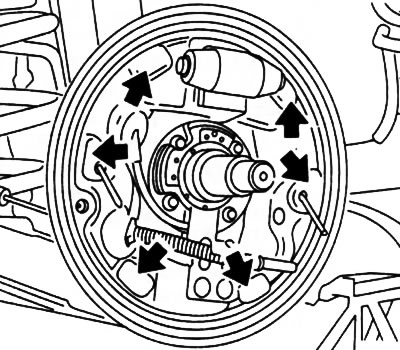
10.18. Points of contact (indicated by arrows) brake shoes with brake shield
Installation
Note: If necessary, periodically check the correct installation of the elements by comparing them with the location on the second (not filmed) brake mechanism.
19. Check that there are no traces of grease or oil stains left on the brake shoes and drum surfaces.
20. Place the parking brake cable in the holder (see accompanying illustration).
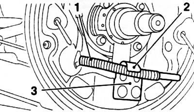
10.20. Insert the parking brake drive cable (1) into the holder (2): 3. Guide
21. Attach the drive cable to the rear shoe and install the shoe onto the brake shield.
22. Insert the rear shoe pressure spring retainer through the hole on the rear side of the brake shield into the hole in the brake shoe. Install the spring with the plate, press the plate with a special tool or pliers. Overcoming the force of the spring, turn the plate at an angle of 90° and fix it.
Note: When performing this operation, it is necessary to hold the retainer from behind.
23. Attach the lower tension spring to both brake shoes, press the lower edge of the front shoe against the guide (see illustration 10.20) and install it on the brake shield. Lubricate the contact areas of the tension spring with heat-resistant paste.
24. Remove the clamp/belt from the brake cylinder.
25. Check the ease of movement of the adjusting gear and the expansion bar (see illustration 10.9). If necessary, disassemble the adjustment unit and clean it.
26. Lubricate the threads of the adjustment unit with a thin layer of silicone grease.
27. Pull the adjusting gear back until it stops, then loosen it a little again - the gear should not remain in the extreme position.
28. Install the disc spring (see illustration 10.9) adjusting lever. When replacing the brake shoes, install a new disc spring.
29. Spread the upper ends of the brake shoes and insert the adjusting expansion bar between them.
Attention: The expansion bar must be installed with the adjusting gear towards the front brake shoe, and the bar fork must fit into the corresponding groove of the shoe!
30. Secure the front brake shoe with the retaining spring (see paragraph 22).
31. Install the adjusting lever with return spring on the front brake shoe (see illustration 10.7), secure the lower end of the return spring to the shoe.
32. Insert the mounting bracket (see illustration 10.7) into the retainer and press it into the hole in the shoe. Fasten the upper tension spring first to the rear brake shoe, and then use the special tool to tighten it and attach it to the mounting bracket.
33. Before installing the brake drum, unscrew the adjusting gear of the expansion bar until it stops, and install the brake drum on the axle.
34. Further installation is carried out in the reverse order of removal. When tightening the hub nut, observe the requirements given in Chapter 8.
35. Press the foot brake pedal several times until you feel a firm movement - the brake pads are adjacent to the discs and occupy a position corresponding to the operating condition.
36. Proceed in a similar manner to replace the brake shoes of the opposite wheel.
37. Before starting intensive use, allow the brake pads to rub in a little by braking the car several times from 80 km/h to 40 km/h by lightly pressing the pedal. Then allow the brake to cool down.
Note: After replacing the pads, try to avoid sudden braking for approximately 200 km.
Visitor comments