


Contents: Removal ⬇ Installation ⬇
Removal
Remove the gearbox and transfer case (see the relevant chapter).
Place a suitable container to collect any leaking transmission fluid. Using the special tool KM-574 (1), remove the torque converter and sealing ring from the turbine shaft.
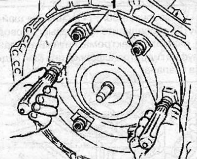
Warning! The torque converter contains a large amount of transmission fluid.
Install the clamping device KM-113-A (3) with the plate KM-113-5 (2) on the base KM-113-2.
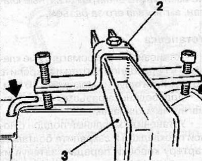
Warning: To avoid damage to the transmission housing, do not overtighten the retaining clamps. Install the short side of the KM-113-5 plate onto the rear of the gearbox housing so that the ventilation tube (arrow) remains free. Place a suitable container to collect any leaking transmission fluid.
Remove the bolt and remove the speed sensor from the gearbox housing.
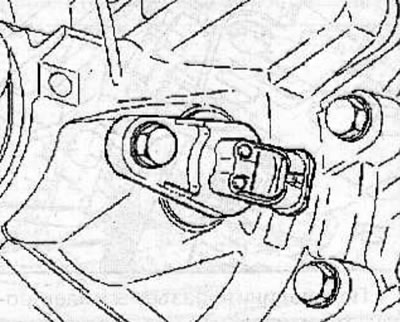
Check the O-ring for wear and damage and replace it if necessary.
Place a suitable container to collect the drained transmission oil.
Remove the plug (arrow) and drain the transmission fluid from the gearbox.
Remove 16 bolts and oil pan (2) from gearbox housing.
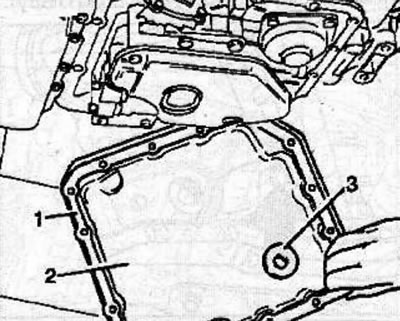
Clean the inside of the oil pan and magnet (3).
Clean the mating surface (1) of the oil pan and gearbox housing.
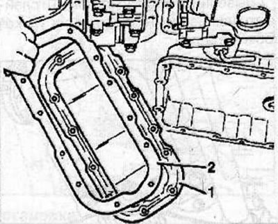
Remove 12 bolts and oil pan adapter (1) and gasket (2) from gearbox housing. Collect any leaking transmission fluid.
Remove the transmission mode switch (see the relevant chapter).
Remove 3 bolts and oil filter (1) and gasket (2).
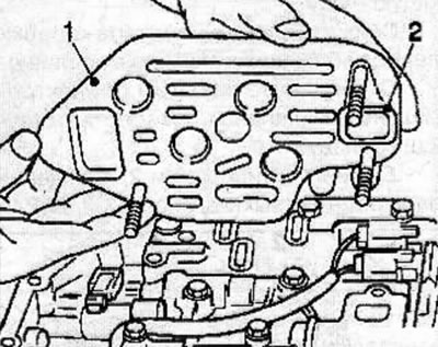
Warning: The gasket is glued to the oil filter and is not supplied separately.
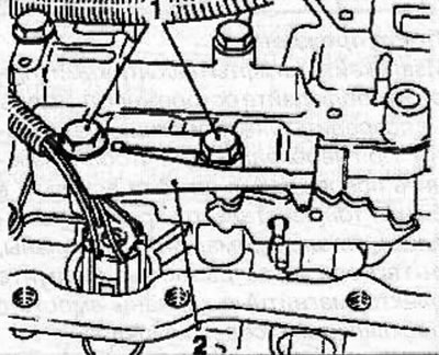
Unscrew the bolts (1) and remove the retainer spring (2) from the gearbox housing.
Use a screwdriver to release the retainer and disconnect the connector (1) from the gearbox housing.
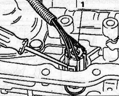
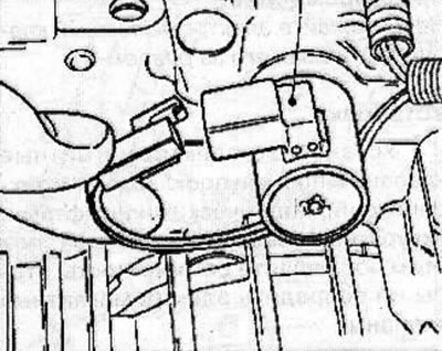
Disconnect the connector from the solenoid valve (1) of the band brake servo.
Use a screwdriver to release the fasteners (1) and disconnect the connectors from the solenoid valves 1/2, 3/4 and 2/3.
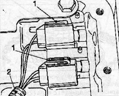
Remove the wiring harness (2).
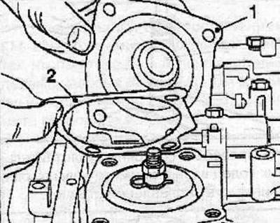
Remove 4 bolts and cover (1) of the band brake servo with gasket (2).
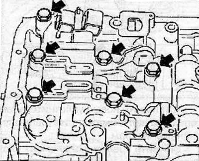
Remove the bolts (arrows) and remove the valve block from the gearbox housing.
Disconnect the ground wire from the valve block.
Raise the valve block slightly and disconnect the control rod (1) from the gearbox mode selection lever (2).
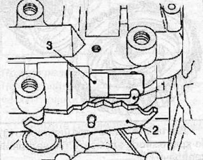
Remove the valve block, gasket and intermediate plate.
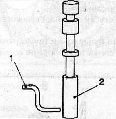
Remove the valve (2) with the control rod (1) from the valve body. Mark the installation position of the control rod. The long end of the rod should be located on the valve side.
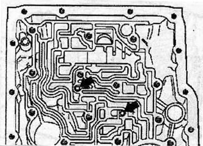
Remove 2 balls (arrows) from the gearbox housing holes and mark the installation position of the balls.
Turn the transmission over and drain any remaining transmission fluid.
Disconnect the connectors from the solenoid valves (1 and 3).
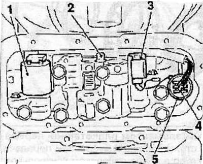
Disconnect the connector (4) from the connector (5) located on the intermediate plate.
Remove the wiring harness from the transmission.
Press the lock (2) and remove the wiring harness in the protective tube going to the pressure regulator control solenoid valve (1).
Unscrew the bolts, disconnect the ground wire and remove the valve block with the support plate (1) and gasket from the adapter housing.
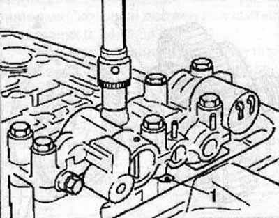
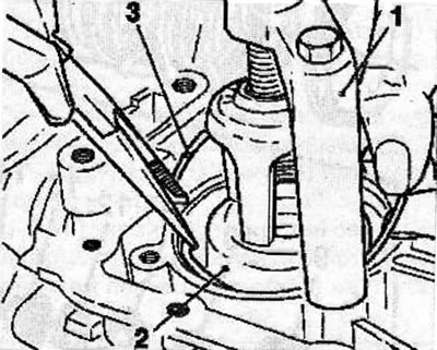
Install the spring compressor KM-J-23075 (1) onto the gearbox housing with the compressor offset towards the rear of the housing. Compress the spring (2) of the band brake servo piston and remove the spring clip (3). Be careful when performing this operation, as the spring is compressed with great force.
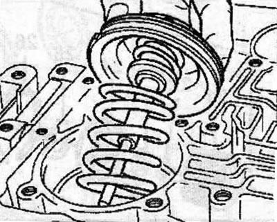
Remove the band brake servo piston assembly.
Installation
Installation is carried out in the reverse order of removal.
Visitor comments