


Contents: Removal ⬇ Installation ⬇
The knock sensor installed on the cylinder block reacts to high-frequency vibrations of the cylinder block and converts them into electrical signals, the value of which increases with increasing detonation. Based on these signals, the engine control unit shifts the ignition timing towards delay, thereby eliminating detonation.
Removal
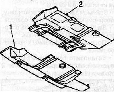
Remove the 2 front bolts and 2 rear nuts securing the lower engine compartment guard (2), then slide it back and disconnect it from the front mudguard (1) of the engine compartment.
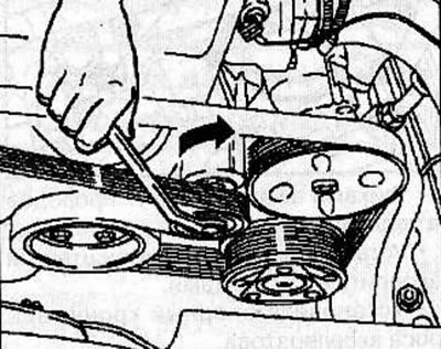
Using a spanner (KM-913-A), turn the belt tensioner roller clockwise by the mounting bolt, thereby loosening the belt tension, and remove the auxiliary drive V-belt.
Remove the air flow meter from the air intake tube.
Remove the engine air temperature sensor from the air intake tube.
Release the clamps and disconnect the air intake tubes from the resonator.
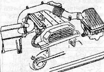
Release the clamps and disconnect the air intake tubes from the air cleaner housing.
Disconnect the air intake tubes from the throttle body.
Disconnect the crankcase ventilation hoses (1) from the cylinder head cover.
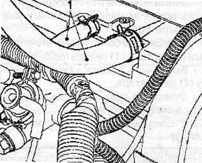
Disconnect the connector from the idle speed control valve (1) located on the throttle body.
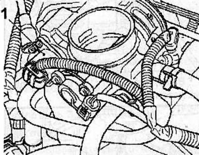
Remove the hollow bolts (1) and disconnect the fuel pipes from the fuel rail.
Disconnect the accelerator cable from the support bracket.
Remove 2 bolts and support bracket.
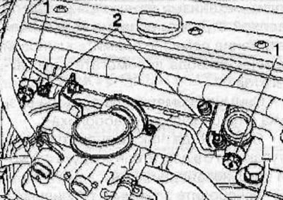
Loosen the nuts securing the wiring harness to the fuel rail.
Unscrew the 2 nuts (2) securing the fuel rail to the intake manifold.
Disconnect the connectors from the fuel rail.
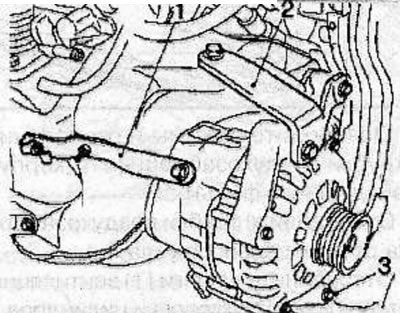
Disconnect the wiring harness from the generator support bracket (1).
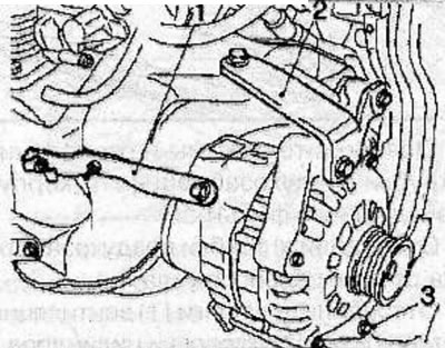
Remove the clamp and disconnect the fuel line from the generator support bracket (1).
Remove 2 bolts and the generator support bracket (1).
Remove 3 bolts and the generator bracket (2).
Unscrew the nuts, remove the bolts (3) and remove the generator.
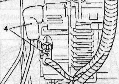
Disconnect the connectors (4) from the generator.
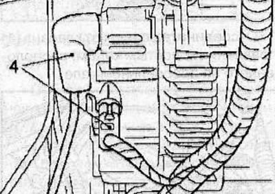
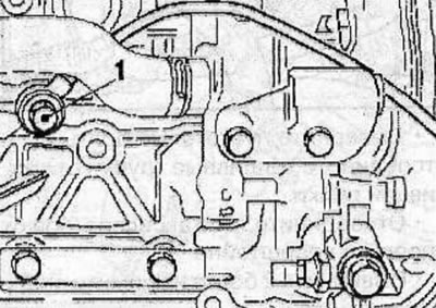
Remove the bolt (1) and remove the knock sensor.
Installation
Install the knock sensor and secure it with the bolt, tightening it to a torque of 20 Nm.
Connect the connectors (4) to the generator.
Install the generator and secure it with bolts (3) and nuts, tightening them to a torque of 35 Nm.
Source is on this resource [OPELBOOK.ru]
Install the generator bracket (2) and secure with 3 bolts, tightening them to a torque of 20 Nm.
Install the generator support bracket (1) and secure with bolts, tightening them to a torque of 20 Nm.
Use a clamp to secure the fuel line to the generator support bracket (1).
Secure the wiring harness to the generator support bracket (1).
Connect the connectors to the fuel rail.
Install the fuel rail onto the intake manifold and secure with 2 nuts (2).
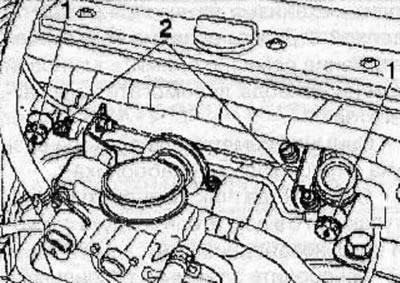
Use nuts to secure the wiring harness to the fuel rail.
Install the support bracket and secure it with 2 bolts.
Install the accelerator cable support bracket.
Connect the fuel lines to the fuel rail and secure them with the hollow bolts (1), tightening them to a torque of 25 Nm.
Connect the connector to the idle speed control valve (1).
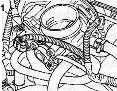
Connect the crankcase ventilation hoses (1) to the cylinder head cover.
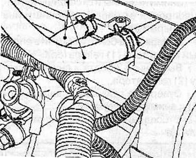
Connect the air intake tubes to the throttle body.
Connect the air intake tubes to the air filter housing.
Connect the air intake tubes to the resonator.
Install the engine air temperature sensor on the air intake pipe.
Install the air flow meter on the air intake tube.
Install the accessory drive V-belt (see the relevant chapter).
Reinstall the lower engine compartment protection.
Visitor comments