


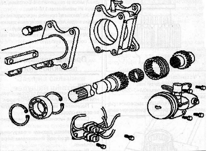
Switching mechanism while driving
Removal
Remove the left drive shaft from the front axle, but do not remove the front axle (see the relevant chapter).
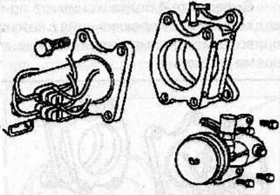
Remove the shift mechanism cover drive while driving (see the relevant chapter).
Remove 4 bolts and shift housing while driving from front axle.
Remove the sleeve with internal teeth (2) and the gear with the hub (3) from the internal drive shaft.
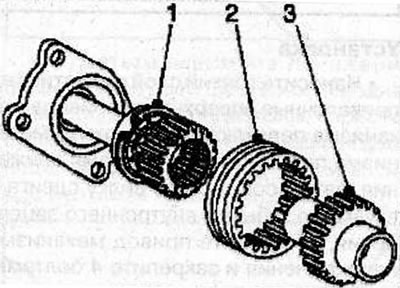
Remove the retaining ring (1) and remove the inner drive shaft from the housing.
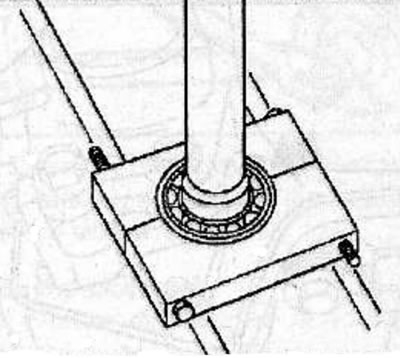
Remove the retaining ring and use the KM-J-22912-01 puller to remove the drive shaft bearing.
Using an inertia hammer and puller KM-J-2694-1, remove the inner needle bearing from the inner drive shaft.
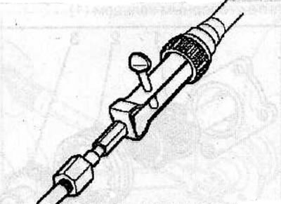
Use a screwdriver to lever the seal out of the drive shaft housing.
Examination
Check all parts for significant wear, damage or corrosion, make necessary repairs or replace damaged parts.
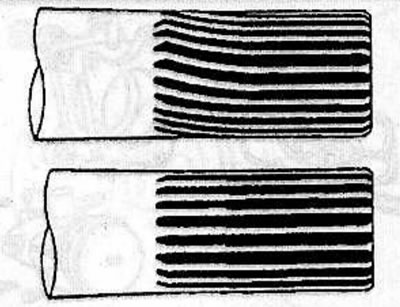
Check that the inner drive shaft is not damaged or shows signs of wear. When checking the inner shaft, make sure that the shaft splines are not twisted, have no signs of wear or damage. If any faults are found, replace the inner shaft.
Place the shaft in the centers and, slowly turning the shaft, measure its radial runout using a pointer-type indicator.
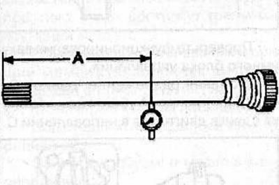
Maximum permissible runout at a distance of 230 mm (A): 0.5 mm
Check the condition of the internal gear bushing and ensure there is no wear, cracks or other damage.
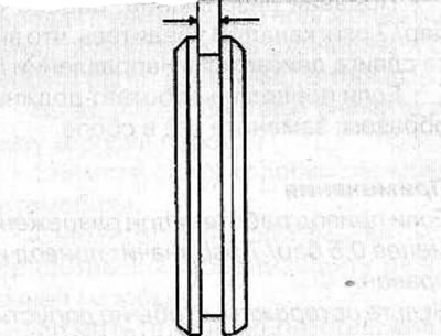
Check the outer groove width of the bushing.
Maximum width: 7.1 mm
Information taken from the website (OpelBook)
Check the movement of the sleeve with internal engagement teeth along the internal shaft together with the gear with the hub. If any difficulty in movement is detected, replace the internal gear bushing.
Note: Apply the recommended oil to the pinion/hub contact surfaces.
Check the gear engagement with the hub for play or excessive wear.
Check the operation of the gear with the hub. If joint movement of the sleeve with internal engagement teeth and the gear with the hub is detected, replace the clutch gear with a new one.
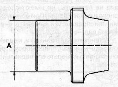
Check the gear hub diameter.
Minimum allowable diameter (A): 36.98 mm
Check the operation of the vacuum control unit.
Apply a vacuum of 0.5 6ap/7 psi to channel A and make sure the shift fork moves in direction C.
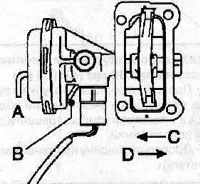
Apply a vacuum of 0.5 bar/7 psi to channel B and ensure that the shift fork moves in direction D.
If the drive does not operate properly, replace the drive assembly.
Notes:
- If the drive operates at a vacuum of less than 0.5 bar/7 psi, then the drive is in good condition.
- Be careful not to allow foreign material to enter the drive vacuum passages.
Check the shift fork.
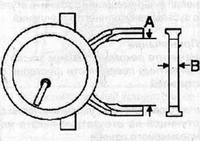
- Size A: no more than 64.1 mm
- Size B: not less than 6.7 mm
Installation
Using tool KM-J-41693 with handle KM-J-8092, install a new oil seal into the drive shaft housing.
Using the KM-41694 tool with the KM-8092 handle, install the needle bearing on the drive shaft.
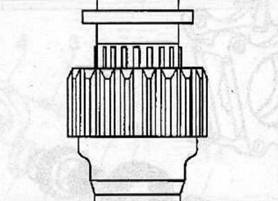
Install the snap ring onto the inner drive shaft.
Press in the bearing using the KM-J-22912-01 tool.
Secure the bearing to the inner drive shaft using the snap ring.
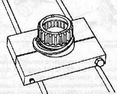
Install the inner drive shaft into the drive shaft housing and secure with the retaining ring (1).
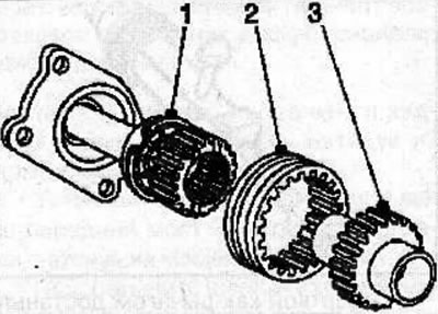
Install the sleeve with internal teeth (2) and the gear with the hub (3) into the drive shaft casing.
Apply a thin layer of sealant 15 03 166 (90 094 714) on the mating surfaces of the shift mechanism housing during movement and the front axle.
Install the shift mechanism cover while driving onto the front axle and secure with 4 bolts, tightening them to a torque of 116 N·m.
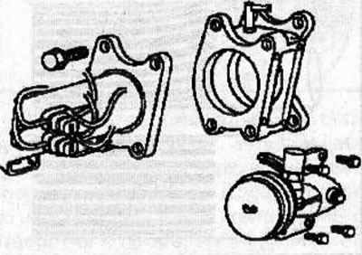
Install the actuator onto the shift mechanism housing while driving (see the relevant chapter).
Install the left drive shaft (see the relevant chapter).
Visitor comments