


Contents: Front wheel alignment angles ⬇ Preparing the car ⬇ Adjusting the front suspension…⬇ Camber adjustment ⬇ Adjusting the transverse tilt of the…⬇ Adjusting the toe-in ⬇ Checking and adjusting the front…⬇ Checking and setting the steering…⬇
Front wheel alignment angles
Wheel alignment is an important parameter when operating a vehicle and has a significant impact on vehicle stability, tire wear and fuel consumption. The following wheel alignment angles are distinguished:
Collapse
Camber is the angle of the wheel in relation to the road surface in the vertical plane. It can be positive if the wheels are tilted outward or negative if the wheels are tilted inward. The camber angle mainly influences lateral forces.
Convergence
Toe-in is defined as half the difference in distance between the front and rear sides of the wheel rims. Positive toe means the front wheels are closer together than the rear wheels when measured at the wheel's midpoint height. Negative toe means that the wheels at the front are further apart than the wheels at the rear. Toe-in affects the straightness of the vehicle's movement and its controllability, and also compensates for the resulting kinematic changes in the suspension geometry under the action of traction force.
The stabilization shoulder is the distance between the contact point of the wheel and the point of intersection of the wheel's steering axis with the road when viewed from the side. Determines the magnitude of the stabilizing moment and affects directional stability and steering forces when cornering.
Transverse tilt of the wheel pivot axis
The transverse caster angle is the angle between the caster axis of the steering knuckle and the vertical drawn through the wheel mounting point, looking in the longitudinal direction of the vehicle. Affects the control force (steering sensitivity) along with other angles.
Due to the camber angles and the transverse tilt of the steering axis, the points of contact of the wheels with the road are located closer to the axis of the steering knuckle. This maintains the so-called "running-in shoulder". The smaller the "running-in shoulder", the easier it is to control the car. Also, impacts from uneven surfaces are less transmitted to the steering wheel.
The longitudinal tilt angle of the pivot axis.
The axis around which the wheel rotates is positioned in space so that its lower part is tilted forward. This angle of longitudinal inclination is called positive. With a positive angle value, the self-return of the wheel to the middle position after a turn is improved.
Preparing the car
- Before testing your vehicle, check and adjust the following if necessary:
- Make sure your vehicle has the correct size wheels and tires;
- Tire pressure;
- Front wheel bearing tension;
- Ball joints of suspension and ball joints of steering rod ends;
- Wheel and tire beating;
- Body installation height (suspension height);
- Reliability of fastening of the steering mechanism to the vehicle frame;
- Shock absorbers for absence of leakage of working fluid or significant extraneous noise;
- Condition of suspension arms and condition of front suspension stabilizer.
For all suspension checks, including toe-in, the vehicle must be on a level, horizontal surface. The front and rear of the car must be at the same height with an acceptable difference between the sides of no more than 6 cm. The car must be in running order with a full fuel tank. Check the ride height using the center line between the front lower control arm bushing and the rear trailing arm upper pivot joint.
Install the suspension angle checking equipment in accordance with the equipment manufacturer's recommendations.
Rock the car body several times so that all suspension elements return to their original position.
Set the steering wheel to the straight-ahead position.
Using special equipment, check all suspension parameters and compare them with technical data.
Adjusting the front suspension mounting height
Note: The front suspension installation height is adjusted using the adjusting bolt (arrow) located on the front suspension torsion bar mount. Turning the adjusting bolt clockwise increases the height of the front suspension.
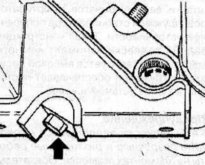
Check and adjust tire pressure when cold.
Measure the front suspension height.
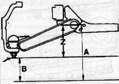
Size Z = A - B
If necessary, adjust the front suspension height by turning the adjusting bolt.
Camber adjustment
Note: Camber adjustment is performed by changing the number of adjusting shims (arrow) installed between the frame and the axle of the suspension arm bushings. The adjusting shims are shaped so that the grooves in them correspond to the location of the 2 bolts securing the front suspension wishbone.
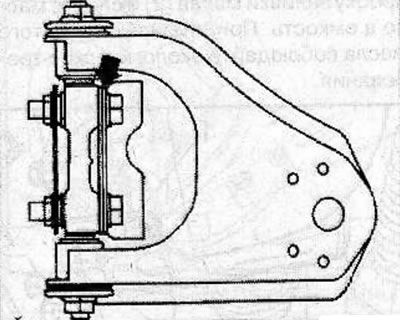
Warnings:
- The total thickness of the shim set must not exceed 10.8 mm.
- The installation angles of the right and left wheels should not differ by more than 30'.
Raise the front of the car so that the front wheels are hanging freely in the air.
Loosen the bolts securing the axle of the upper wishbone bushings of the front suspension to the vehicle body.
To decrease camber, add shims (arrow), and to increase camber, remove the shims already installed.
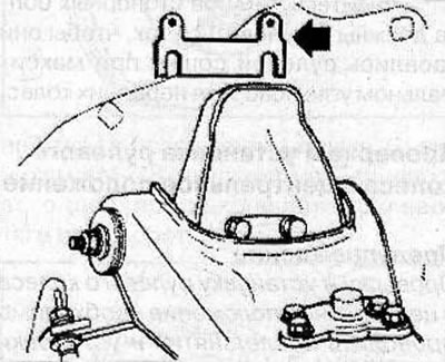
Tighten the front suspension upper wishbone bushing axle mounting bolts to 155 N·m.
Lower the car onto its wheels and rock the car body several times until all suspension elements return to their original position.
Recheck the front wheel alignment.
Adjusting the transverse tilt of the steering axis
Note: The lateral tilt of the steering axis is adjusted by changing the number of adjusting shims (arrow) installed on the bolts between the frame and the axle of the suspension arm bushings. The adjusting shims are designed to fit over the front suspension wishbone mounting bolts.
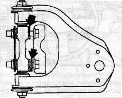
Warnings:
- The total thickness of the adjustment shim set must not exceed 10.8 mm.
- The difference in thickness of the adjusting shims on the front and rear bolts should not exceed 3.2 mm.
- The installation angles of the right and left wheels should not differ by more than 30'.
Raise the front of the vehicle so that the corresponding front wheel hangs freely in the air.
Loosen the bolts securing the axle of the upper wishbone bushings of the front suspension to the vehicle body.
To reduce the steering axis tilt, add shims (arrow) to the front bolt or remove shims from the rear bolt.
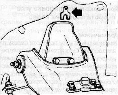
To increase the steering axis caster, add shims to the rear bolt or remove shims from the front bolt.
Tighten the front suspension upper wishbone bushing axle mounting bolts to 155 N·m.
Lower the car onto its wheels and rock the car body several times until all suspension elements return to their original position.
Recheck the steering axis caster and front wheel camber and adjust the camber if necessary.
Adjusting the toe-in
Warning: To keep the steering wheel in the center position, turn the threaded inserts of the right and left steering rods by the same angle during adjustment.
Place the vehicle on a stand to measure the front wheel alignment.
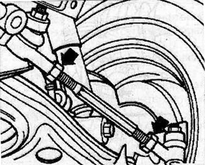
Loosen the locknuts of the steering rod threaded inserts and, by rotating the threaded inserts, adjust the toe-in of the front wheels.
Note: Nuts marked L have left-hand threads.
Tighten the locknuts of the steering rod threaded inserts to a torque of 120 Nm.
Recheck the front wheel alignment.
Checking and adjusting the front wheel steering angle
Note: The maximum front wheel steering angles should be set after toe adjustment. The maximum steering angle of the wheels is adjusted by changing the length of the locking bolt (arrow) located above the front pivot bolt in the lower wishbone of the front suspension.
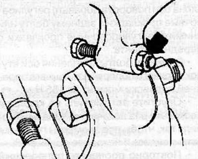
Warning! Adjustment of the maximum front wheel steering angle is performed after all other front wheel alignment angles have been adjusted.
Original posted on the website opelbook
Place the front wheels of the vehicle on a turning device.
Set the front wheels to the straight ahead position.
Apply the parking brake.
Loosen the lock nuts and, by turning the lock bolts, set the maximum turning angle of both front wheels of the car.
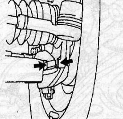
Tighten the lock nuts of the lock bolts to a torque of 23 N·m.
Make sure that the stops on the lower control arm and steering knuckle (arrows) do not touch each other when the front wheels are fully turned.
Make sure both lock bolts are installed so that they touch the steering arm at maximum front wheel steering angle.
Checking and setting the steering wheel to the center position
Warning! Checking and setting the steering wheel to the center position must be carried out after removing and installing the steering gear and steering column.
The steering wheel should be in the central position after adjusting the toe-in and setting the length of the right and left steering rods to the dimension L equal to 299 mm.
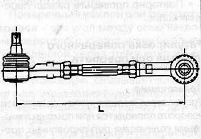
In this case, the steering wheel should be in the central position.
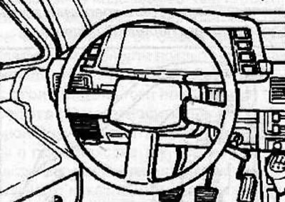
If necessary, remove the steering wheel and set it to the center position (see the relevant chapter).
Visitor comments